semi合集-English.pdf - 第3799页
SEMI F11-0998 © SEMI 1993, 1998 3 Figure 2 Thermal Transition Chart 9.4 Lower t he fluid temperature to 25° C (77° F) for a total of two hours. The maximum time allo wed to achieve the 25° C (77° F) te mperature conditio…
SEMI F11-0998 © SEMI 1993, 1998 2
6 Description of Test Equipment
6.1 A hydraulic system capable of applying a constant
internal hydraulic pressure to all test specimens while
allowing a uniform fluid flow rate through each
specimen.
6.1.1 The pressure capability shall range from 100 to
1200, ± 35 kPa (15 to 174, ± 5 psig).
6.1.2 The fluid flow rate shall be adequate to maintain
the fluid temperature at each specimen to ± 2.8° C (±
5° F) of the specified fluid temperature.
6.1.3 The fluid temperature capability shall range from
25° C to 200° C (77° F to 392° F), within a one hour time
interval from hot to cool and vice versa.
6.2 An enclosure that will allow observation of the test
specimens and is capable of controlling the ambient
temperature to 31° ± 6° C (88° ± 11° F).
6.3 An instrument to monitor pressure within ± 1% of
full scale.
6.4 An instrument to monitor temperature within ± 1° C
(2° F).
6.5 An instrument to monitor time.
6.6 Specimen Support — Any support is acceptable as
long as it does not contribute to the restraint of the
specimen in either the circumferential or axial direction.
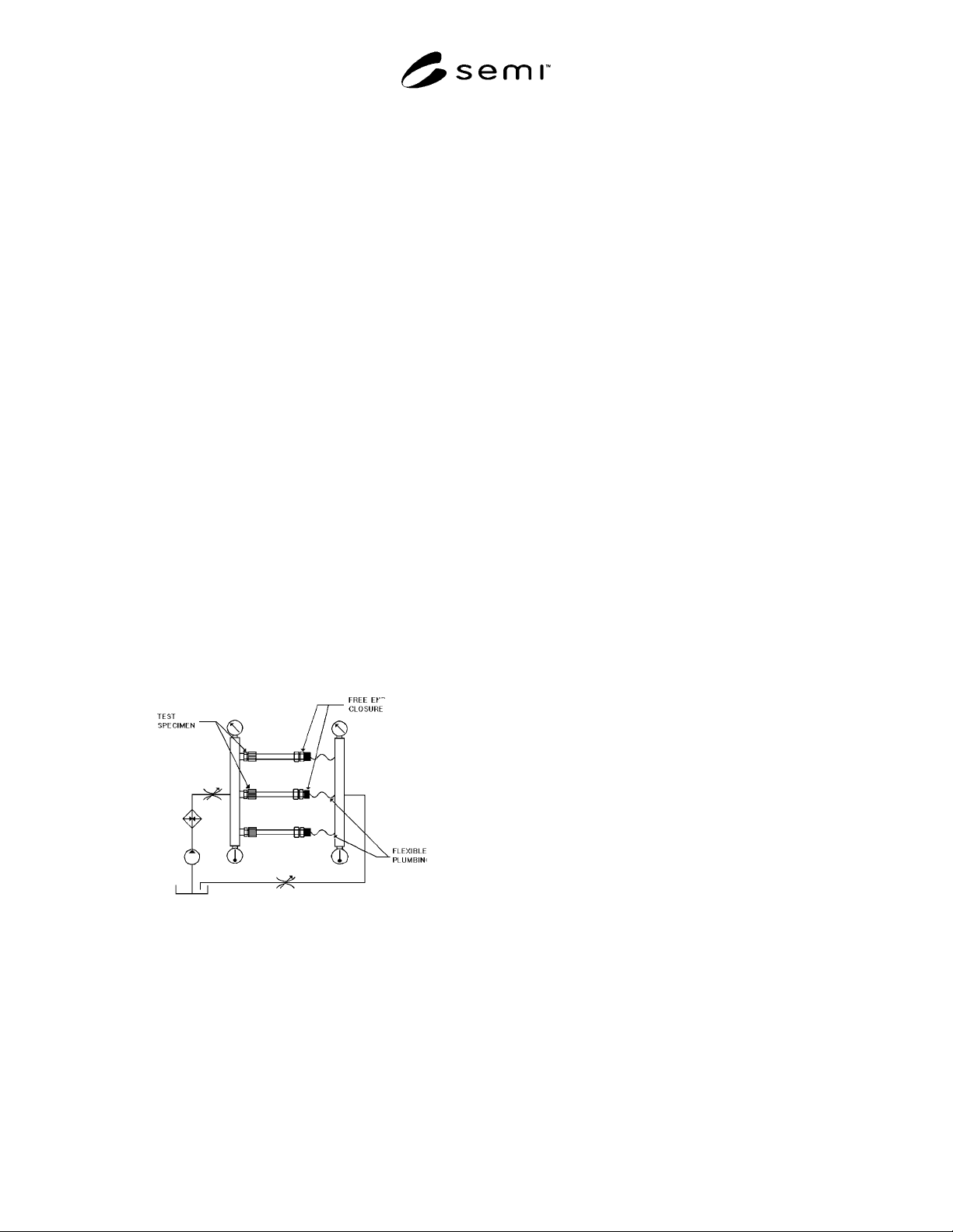
6.7 See Figure 1 for basic test system.
Figure 1
Basic Test System
7 Safety Precautions
WARNING: This test method will subject test
specimens to conditions that may exceed the
normal performance ratings of the products
under evaluation. Adequate precautions must
be taken to prevent injury to the person
conducting the test. The hydraulic plumbing
and safety enclosure are to be constructed of
materials which are capable of containing a
fluid at 200°C (392°F).
8 Test Specimens and Conditioning
8.1 Sample Size — A minimum of three specimens
shall be tested at each pressure condition.
8.2 Specimen Surface — All surfaces of the specimens
shall be free of visible flaws, scratches, or other
imperfections, unless typically found on a
representative sample of the product.
8.3 Specimen Conditioning — All specimens must be
conditioned for a minimum of one hour in an air
environment of 23° ± 2.8° C (73° ± 5° F) prior to being
subjected to pressure.
9 Test Procedure
9.1 Install three fitting connections, assembled per
manufacturer’s specifications, to the test manifold.
Allow for a minimum of 30 cm (12 in) of tube length
between the test fitting connection and free end closure.
(See Figure 1.)
9.1.1 The apparatus should include a section of flexible
line from the free end enclosure to return manifold to
allow for expansion.
9.2 Circulate 25° C (77° F) fluid through the test
samples with a constant pressure of 100 kPa (15 psig)
for one hour.
9.2.1 When three failures occur at any given pressure
during the initial room temperature condition (prior to
the specimens having been subjected to any elevated
temperature conditions), testing is terminated.
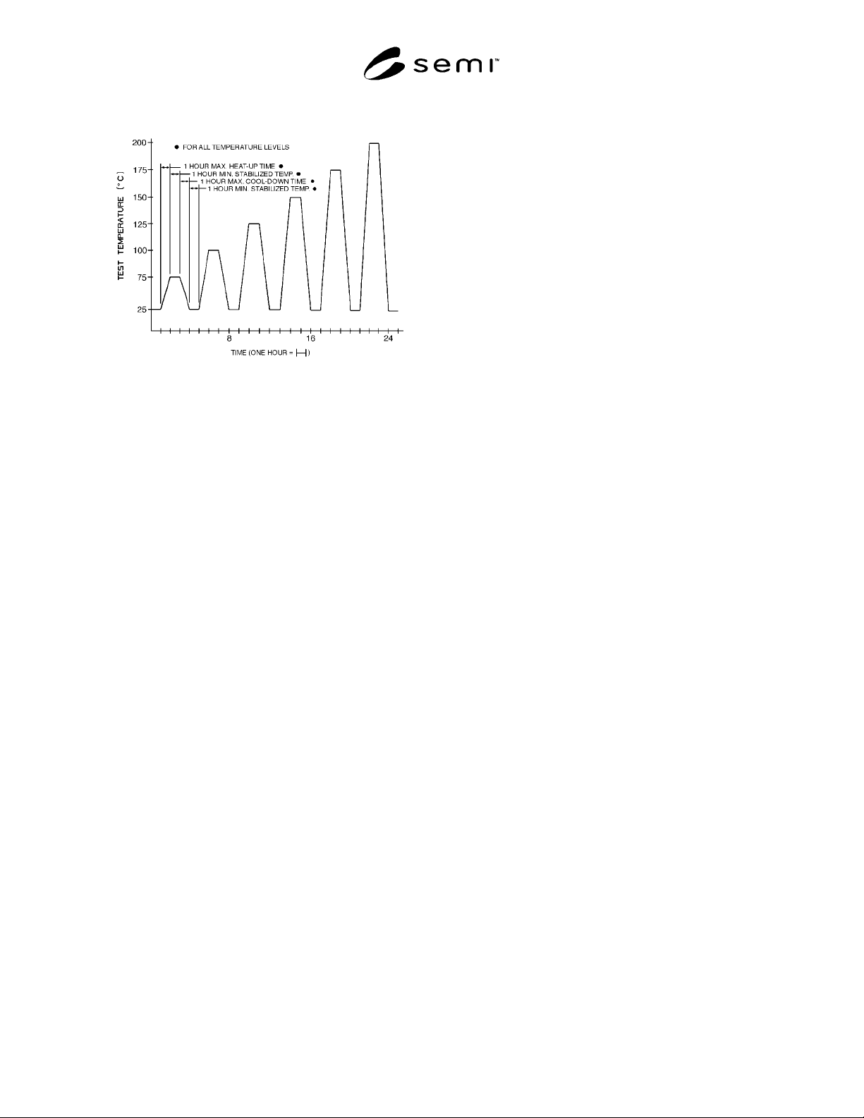
9.3 Increase the fluid temperature to 75° C (167° F) for
a total time of two hours from the time the temperature
was initially increased. The maximum time allowed to
achieve the elevated temperature is one hour. (See
Figure 2.)
SEMI F11-0998 © SEMI 1993, 1998 3
Figure 2
Thermal Transition Chart
9.4 Lower the fluid temperature to 25° C (77° F) for a
total of two hours. The maximum time allowed to
achieve the 25° C (77° F) temperature condition is one
hour.
9.5 Repeat Sections 9.3 and 9.4, substituting, for the
fluid temperature in Section 9.3, the remaining five
temperatures: 100° C (212° F), 125° C (257° F), 150° C
(302° F), 175° C (347° F), and 200° C (392° F).
9.5.1 The test samples should be at 25° C (77° F) prior
to stopping the test at the end of a work shift.
9.5.1.1 The two hours at 25° C (77° F) will be equally
divided between the present day cool-down time and
the next day start-up time.
9.6 Monitor each of the three connections for external
leakage throughout all test parameters.
9.7 Any external leakage at a tube connection will be
recorded as a failure on the test data sheet (see Related
Information 1 for sample test data sheet).
9.7.1 Leakage observed, once an elevated temperature
is reached, will be recorded as a failure at that
temperature.
9.7.2 Leakage at or during the cool-down cycle is to be
recorded as a failure of the previously tested elevated
temperature condition.
9.7.3 Leakage observed while increasing the
temperature to the next condition is to be recorded as a
failure of the previous elevated temperature condition.
9.8 Once a connection shows leakage and its failure
pressure and temperature has been recorded, any
additional leakage is not taken into consideration.
9.8.1 If leakage is not excessive, the connection can
remain in the system until testing at that pressure has
been completed.
9.8.2 If leakage of a connection becomes excessive, the
connection may be retightened or replaced in order to
continue testing of the remaining specimens. Take
precautions not to disturb the remaining test specimens.
WARNING: Due to the extreme danger of high
temperature fluids, take all necessary precautions
when retightening or replacing a connection, to
prevent accidental exposure to the heated fluid.
9.9 After three connection failures are recorded, or the
200° C (392° F) temperature has been achieved, a new
set of fittings is to be installed for the next pressure
condition.
9.10 Repeat Sections 9.2 through 9.9 for the remaining
six pressures: 200 kPa (29 psig), 400 kPa (58 psig), 600
kPa (87 psig), 800 kPa (116 psig), 1000 kPa (145 psig),
and 1200 kPa (174 psig).
10 Data Accuracy
10.1 Fluid Temperature — ± 1° C (± 2° F)
10.2 Pressure — kPa: ± 2%
11 Test Data Sheet
The test data sheet shall include the following
information:
11.1 Date tested.
11.2 Operator and test facility.
11.3 Description of items tested, including:
Tubing — Manufacturer, O.D., wall thickness, part
number, and material type.
Fitting — Manufacturer, type, size, part number, and
material type.
11.4 The actual temperatures and pressures at which
failures occur.
NOTE: A sample test data sheet is provided as Related
Information 1.

SEMI F11-0998 © SEMI 1993, 1998 4
NOTICE: These standards do not purport to address
safety issues, if any, associated with their use. It is the
responsibility of the user of these standards to establish
appropriate safety and health practices and determine
the applicability of regulatory limitations prior to use.
SEMI makes no warranties or representations as to the
suitability of the standards set forth herein for any
particular application. The determination of the
suitability of the standard is solely the responsibility of
the user. Users are cautioned to refer to manufacturer’s
instructions, product labels, product data sheets, and
other relevant literature respecting any materials
mentioned herein. These standards are subject to
change without notice.
The user’s attention is called to the possibility that
compliance with this standard may require use of
copyrighted material or of an invention covered by
patent rights. By publication of this standard, SEMI
takes no position respecting the validity of any patent
rights or copyrights asserted in connection with any
item mentioned in this standard. Users of this standard
are expressly advised that determination of any such
patent rights or copyrights, and the risk of infringement
of such rights, are entirely their own responsibility.