semi合集-English.pdf - 第456页
SEMI E66-1103 © SEMI 1997, 2003 5 8.12 Fittings — Face seal connectors or c o mpression fittings, depending on test component end connections. The end connection fittings of each DUT being compared must be of the same ty…
SEMI E66-1103 © SEMI 1997, 2003 4
cone between 6.35 mm and 12.7 mm (1/4 in. and 1/2 in.) face-seal connections.
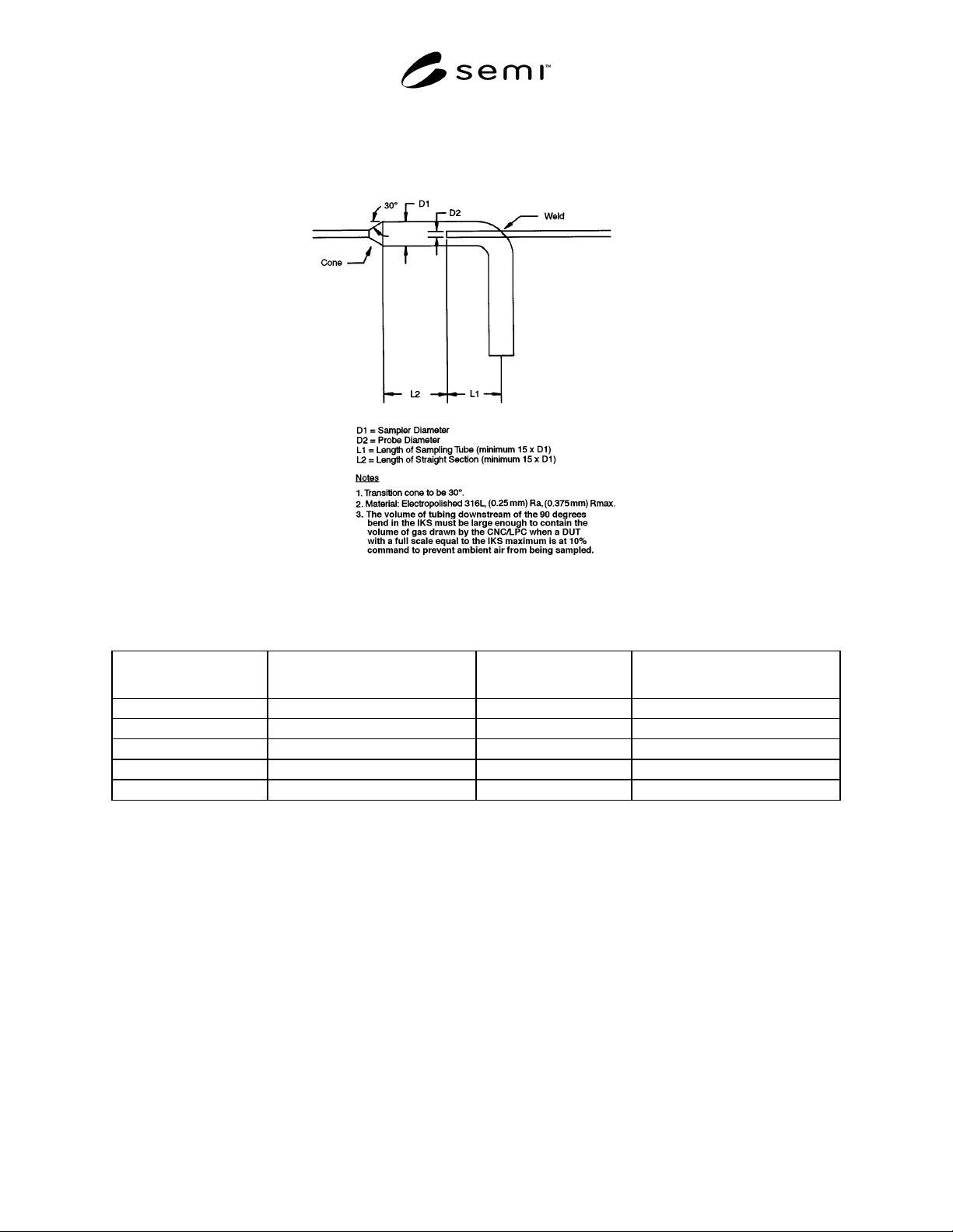
Figure 3
Isokinetic Sampler Design
Table 1
Maximum IKS Inlet Flow
(liters/min.)
ID Probe D
2
(note)mm (inches)
ID Sampler D
1
- mm
(inches)
Worst-Case Dilution
300 4.62 (0.180) 68.58 (2.700) 3:1
100 4.62 (0.180) 39.62 (1.560) 3:1
30 4.62 (0.180) 21.44 (0.844) 3:1
10 4.62 (0.180) 11.99 (0.472) 3:1
3 7.75 (0.305) 12.57 (0.495) 2:1
NOTE 1: For 300,000 to 10,000 cc/min. test flow:
• Constant sample velocity = 132 cm/sec.
• D2 = 4.57 mm (0.180 in.) ID standard 6.35 mm (1/4 in.) tubing (see Figure 3)
• For 1.41 l/min. CNC
NOTE 2: For 3,000 cc/min. test flow:
• Constant sample velocity = 49.9 cm/sec.
• D
2
= 7.75 mm (0.305 in.) ID standard 9.53 mm (3/8 in.) tubing (see Figure 3)
• For 1.41 l/min. CNC
8.10 Downstream Adapter — To connect 12.7 mm (1/2 in.) sampler tubing to the test device. For 12.7 mm (1/2 in.)
test devices, the adapter is a simple face-seal connector. For 6.35 mm (1/4 in.) test devices, the adapter is a tapered
cone between 6.35 mm and 12.7 mm (1/4 in. and 1/2 in.) face-seal connections.
8.11 Spool Pieces — Of the same inside diameter as the inside diameter fittings on the test piece and of a length
representative of the DUT, to be installed in the system in place of the test device while obtaining background
counts for the system.
SEMI E66-1103 © SEMI 1997, 2003 5
8.12 Fittings — Face seal connectors or compression fittings, depending on test component end connections. The
end connection fittings of each DUT being compared must be of the same type.
8.13 Metal Gaskets — New gaskets should be used for each new connection.
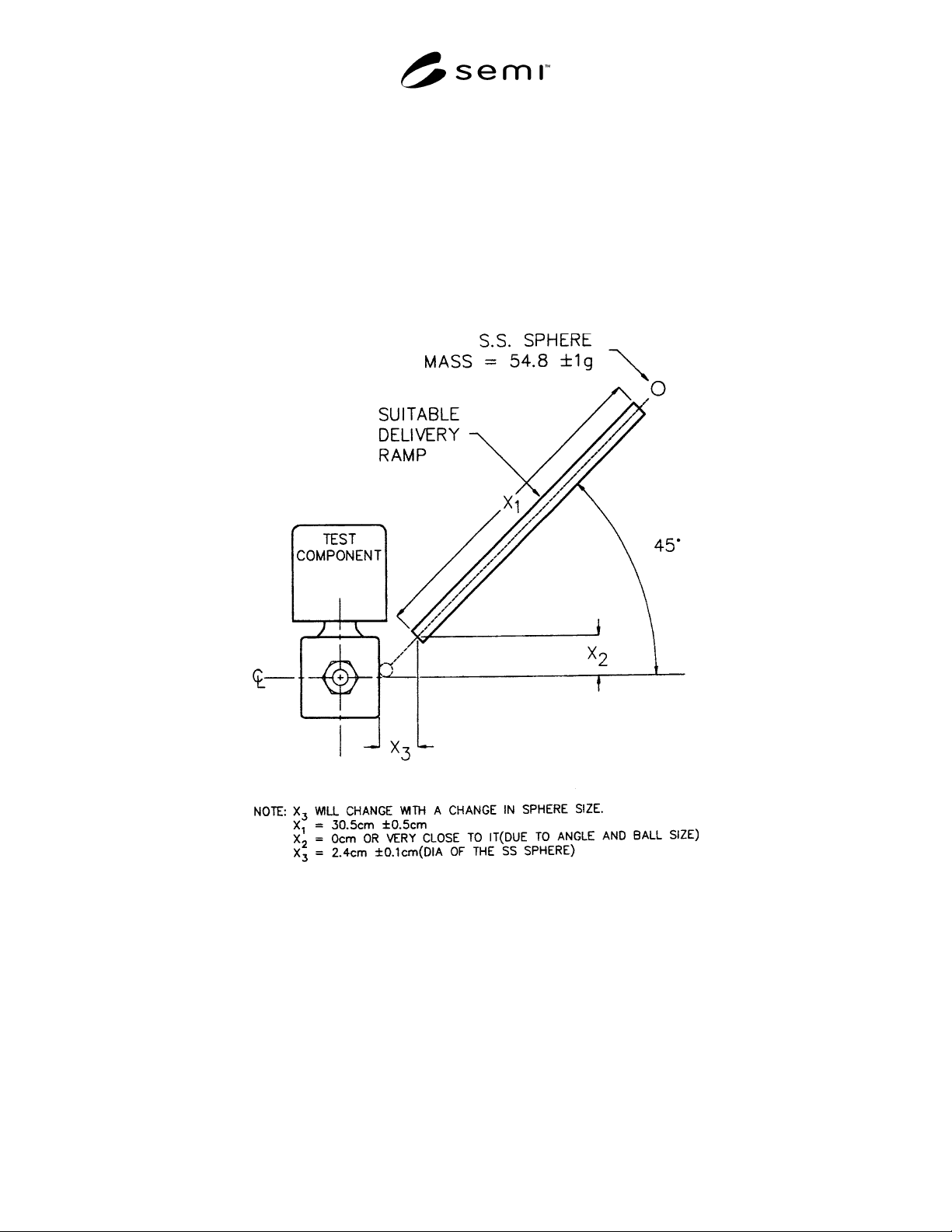
8.14 Mechanical Shock Device — To provide mechanical shock by impact to the test device. (See Figure 4.)
8.15 Instrumentation — Condensation nucleus counter (CNC) or laser particle counter (LPC) to collect particle
count data.
8.16 Isokinetic Sampler (IKS) — A static device used to collect a representative sample that is not influenced by
flow characteristics and/or particle size (see Figure 3). Other designs of isokinetic samplers are permitted as long as
they collect a representative sample of the flow.
Figure 4
Mechanical Shock Test Device
NOTE: Position the delivery ramp so that the position of impact is at the midpoint of the axial centerline of the device under test.
9 Sampling, Test Specimens, and Test Units
9.1 MFCs regulate flows greater than or less than the flow requirements of particle counters; therefore, two
different sampling techniques have been defined, isokinetic sampling and direct sampling.
9.1.1 Direct Sampling — The direct sampling method is used when the test flow is less than or equal to the sample
flow. (See Figure 1.)
9.1.1.1 In this case, gas exiting the DUT is introduced directly into the CNC. A tee, equipped with a filtered branch,
is inserted between the DUT and the CNC to provide make-up flow to the CNC. The volume and overall length of
the tubing connecting the DUT to the tee assembly should be minimized.

SEMI E66-1103 © SEMI 1997, 2003 6
9.1.2 Isokinetic Sampling — Isokinetic sampling is
used when the test flow is greater than the sample flow.
(See Figure 2.)
NOTE 1: An alternative size IKS may be substituted for the
IKS described in Sections 9.1.2.1 through 9.1.2.7 as long as it
collects a representative sample of particles that is not
influenced by flow characteristics and/or particle size.
9.1.2.1 Select the appropriate IKS (see Figure 3) from
Table 1 for the test flow. This is the smallest IKS that
exceeds the flow of the DUT.
9.1.2.2 The average velocity of the gas through the
sampling probe shall approximate the average velocity
in the tubing in which the sampling probe is inserted.
The sample flow used to calculate the sampling probe
diameter is the total flow drawn by the counter.
9.1.2.3 The tip of the sampling probe is to have a 30_
taper on the outside diameter.
9.1.2.4 The pick-off point is to be centered within the
flow stream.
9.1.2.5 The pick-off point is to be at a minimum
distance of 15 diameters of the primary flow tube
upstream or downstream from any connection.
9.1.2.6 Flow stability within the isokinetic sampler is
maintained by the bypass MFC.
9.1.2.7 To determine the dimensions of the isokinetic
sampler, as shown in Table 1, the following equations
and conditions are used:
10 Preparation of Apparatus
10.1 Setup and Schematic for Direct Sampling — See
Figure 1.
10.1.1 Install the spool piece between points A and B.
10.1.2 Set nominal supply pressure to 308.10 kPa (30
psig).
10.1.3 Cycle the supply MFC, switching between a low
flow and maximum purge flow as quickly as is
reasonably possible. Cycle every five seconds for at
least 30 minutes. The maximum purge flow should be
as high as possible and no less than twice the test rate.
During this initial cleanup, the particle counter should
be off-line.
10.1.4 Moisture from an inboard leak can cause
particle counts on some particle counters. Test the
system for leak integrity per SEMI F1 – Subsystems
Inboard Leak Test.
10.2 Setup and Schematic for Isokinetic Sampling —
See Figure 2.
10.2.1 Install the spool piece between points A and B.
10.2.2 Set nominal supply pressure to 308.10 kPa (30
psig).
10.2.3 Cycle the supply MFC, switching between a low
flow and maximum purge flow as quickly as is
reasonably possible. Cycle every five seconds for at
least 30 minutes. The maximum purge flow should be
as high as possible and no less than twice the test rate.
During this initial cleanup, the particle counter should
be off-line.
10.2.4 Moisture from an inboard leak can cause
particle counts on some particle counters. Test the
system for leak integrity per SEMI F1 – Subsystems
Inboard Leak Test.
10.3 Select the appropriate isokinetic sampler based on
the maximum test flow of the DUT, using Table 1 and
Figure 3. The size of the sampler should be equal to or
greater than the maximum test flow.
11 Calibration and Reference Standards
11.1 Calibrate instruments regularly according to the
manufacturer’s recommendations.
12 Test Procedure
The test apparatus is to be enclosed in a Class 100
environment (in accordance with ISO 14644). Test
must be performed in the sequence described below.
(See Figures 5 and 6.)
Measure DUT in purge mode to determine flow or use
the value supplied by the manufacturer. This will
determine which apparatus to use, direct sampling
(Figure 1) or IKS (Figure 2). Both of the test apparatus
may be required for testing a wide range of flow
controllers.