semi合集-English.pdf - 第4098页
SEMI F59-0302 © SEMI 2000, 2002 4 the desi red flow rate and inl et pressu re. T he f low rat e is read on th e flow meter and recorded. 14.2.4 Read and record the ambien t temperatu r e, ambi ent press ure, inlet press …

SEMI F59-0302 © SEMI 2000, 2002 3
for pressure drop measurement. The gas stick may be
removed from the pallet to attach to the test fixture.
11.2 Pressure regulators and MFCs shall be maintained
in their fully open position during testing.
11.3 When comparing different gas system designs, it
is useful to use components of similar design.
11.4 If the stick design contains a filter that dominates
the pressure drop on the system, such filters shall be
replaced by spool flow through components
12 Preparation of Apparatus
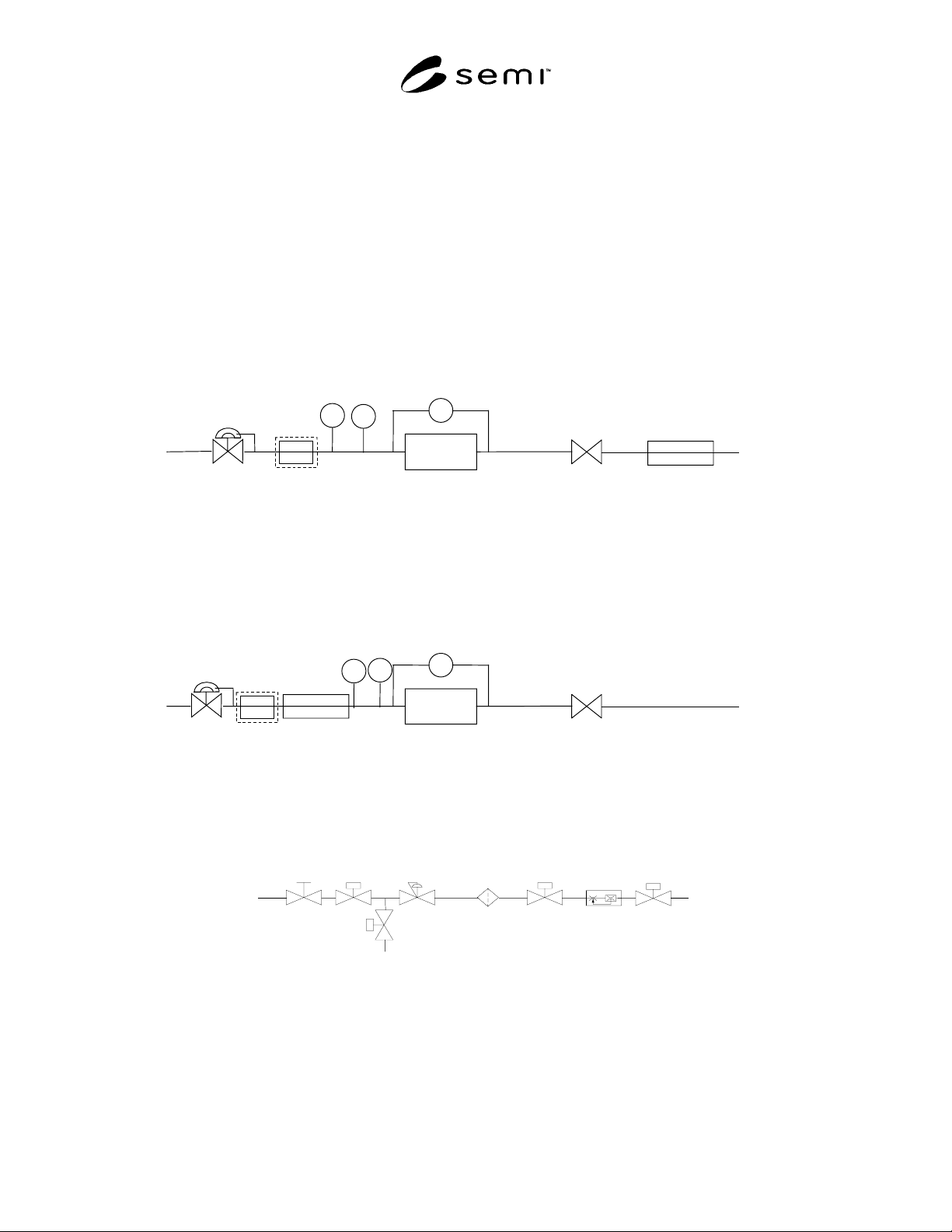
12.1 Construct a test stand for the measurement of gas
flow rates and pressure drop across a DUT. Examples
of such a test stand are shown in Figures 1a or 1b as
schematic drawings.
12.2 The gas supply is filtered by an electronics grade
high purity point-of-use gas filter before it is delivered
to the DUT through a pressure regulator.
12.3 A flow meter can be installed either upstream or
downstream of the DUT. See Figures 1a or 1b. The
test filter is upstream of a throttle valve to allow for
control of the flow through the DUT.
12.4 Inlet pressure is measured immediately upstream
of the DUT by a pressure gauge or pressure transducer.
12.5 Pressure drop across the test specimen is
measured by an electronic differential pressure
transducer capable of reading 0.67 kPa (0.1 psid) across
the test device.
12.6 Flow measurements are carried out through a flow
meter installed upstream or downstream of the test
filter. See Figures 1a or 1b.
NOTE 2: The flow measurement can be influenced by both
upstream and downstream pressure fluctuations. It is
necessary to verify the accuracy of any flow measurement
under the test conditions used to complete this testing.
12.7 A temperature measurement device can be
installed in the test stand to measure the gas stream
temperature.
12.8 Figure 2 gives the piping requirements for the test
stand configuration.
12.9 Figure 3 gives the recommended pressure
connection to be followed in constructing the test
apparatus.
13 Calibration and Standardization
13.1 For each test, verify that calibration of test
equipment is up-to-date.
13.2 A series of flow meters should be used to cover
the full range of flows that will be tested.
14 Procedure
14.1 Integral Filtration Unit
14.1.1 Assemble the filtration unit into the test
apparatus. (See Figure 1.)
14.1.2 Set the inlet pressure using the pressure
regulator to 10% of the filter’s maximum rated inlet
pressure or to 205 kPa (29.7 psia) whichever is less.
Pressure is read on the inlet pressure gauge.
14.1.3 Adjust the flow rate using the regulating valve
to give 10 % of the maximum rated flow. Adjustments
to the inlet pressure regulator may be required to
maintain a constant inlet pressure of 205 kPa (29.7
psia). The flow and pressure adjustments can be an
iterative process requiring several iterations to achieve
the desired flow rate and inlet pressure. The flow rate
is read on the flow meter and recorded.
14.1.4 Read and record the ambient temperature, inlet
pressure, pressure drop across the test filter, ambient
pressure, and flow rate corrected for upstream pressure
based on manufacturer’s recommendation.
14.1.5 Repeat steps in Sections 14.1.3 and 14.1.4 at
25%, 50%, 75% and 100% of the maximum rated flow.
14.1.6 Repeat steps in Sections 14.1.2 through 14.1.5
at several inlet pressures: 309 kPa (44.7 psia), 516 kPa
(74.7 psia), and 723 kPa (104.7 psia).
14.1.7 Additional testing of the filter at higher
pressures can be completed up to the maximum rated
pressure.
14.1.8 When the filter has a lower maximum pressure
rating than 90 psig, it is recommended that the filter be
tested at pressures of 33%, 67% and 100% of the
filter’s maximum pressure rating, with tests being
limited by the sensitivity of the differential pressure
device.
14.2 Separable Filtration Unit - Filter Housing
14.2.1 Assemble the empty filter housing into the test
apparatus.
14.2.2 Set the inlet pressure using the pressure
regulator to 10% of the housing’s maximum rated inlet
pressure or to 205 kPa (29.7 psia) whichever is less.
The inlet pressure is read on the inlet pressure gauge
and recorded.
14.2.3 Adjust the flow rate using the regulating valve
to give 10% of the maximum rated flow. Adjustments
to the inlet pressure regulator may be required to
maintain a constant inlet pressure of 205 kPa (29.7
psia). The flow and pressure adjustments can be an
iterative process requiring several iterations to achieve

SEMI F59-0302 © SEMI 2000, 2002 4
the desired flow rate and inlet pressure. The flow rate
is read on the flow meter and recorded.
14.2.4 Read and record the ambient temperature,
ambient pressure, inlet pressure, pressure drop across
the test filter, and flow rate corrected for upstream
pressure based on manufacturer’s recommendation.
14.2.5 Repeat steps in Sections 14.2.3 and 14.2.4 at
25%, 50%, 75%, 100% of the filter cartridge’s
maximum rated flow.
14.2.6 Repeat steps in Sections 14.2.2 through 14.2.5
at several inlet pressures. For example, test at 309 kPa
(44.7 psia), 516 kPa (74.7 psia), and 723 kPa (104.7
psia).
14.2.7 Additional testing of the filter at higher
pressures can be completed up to the maximum rated
pressure.
14.2.8 When the filter has a lower maximum pressure
rating than 90 psig, it is recommended that the filter be
tested at pressures of 33%, 67% and 100% of the
filter’s maximum pressure rating, with tests being
limited by the sensitivity of the differential pressure
device.
14.3 Separable Filtration Unit – Assembled Cartridge
and Housing
14.3.1 Assemble the filter cartridge into the filter
housing.
14.3.2 Assemble the filtration unit into the test
apparatus.
14.3.3 Set the inlet pressure using the pressure
regulator to 10% of the filter’s maximum rated inlet
pressure, or to 205 kPa (29.7 psia), whichever is less.
The inlet pressure is read on the inlet pressure
gauge/transducer and recorded. This pressure should be
the same as used for the filter housing test in Section
14.2.2.
14.3.4 Adjust the flow rate using the regulating valve
to give 10% of the maximum rated flow. Adjustments
to the inlet pressure regulator may be required to
maintain a constant inlet pressure of 205 kPa (29.7
psia). The flow and pressure adjustments can be an
iterative process requiring several iterations to achieve
the desired flow rate and inlet pressure. The flow rate
is read on the flow meter and recorded. This should be
the same as used for the filter housing test in Section
14.2.3.
14.3.5 Read and record the ambient temperature,
ambient pressure, inlet pressure, pressure drop, and
flow rate.
14.3.6 Repeat steps in Sections 14.3.3 and 14.3.5 at
25%, 50%, 75% and 100% of the maximum rated flow.
These should be the same flow settings as used in
Section 14.2.5.
14.3.7 Repeat steps in Sections 14.3.2 through 14.3.6
at several inlet pressures. For example, test at 309 kPa
(44.7 psia), 516 kPa (74.7 psia), and 723 kPa (104.7
psia).
14.3.8 Additional testing of the filter at higher
pressures can be completed up to the maximum rated
pressure. These inlet pressure settings should be the
same as used in Section 14.2.7.
14.3.9 When the filter has a lower maximum pressure
rating, it is recommended that the filter be tested at
pressures of 33%, 67% and 100% of the filter’s
maximum pressure rating, with tests being limited by
the sensitivity of the differential pressure device.
14.3.10 The flow curve for the filter cartridge is
determined by subtracting the pressure drop of the
housing from the pressure drop of the assembled
filtration unit at respective flow rates and inlet test
pressures.
14.4 Gas System
14.4.1 Assemble the DUT into the test apparatus. (See
Figure 1.)
14.4.2 Set the inlet pressure using the pressure
regulator to 205 kPa (29.7 psia). Pressure is read on the
inlet pressure gauge.
14.4.3 Adjust the flow rate using the regulating valve
to give 1 slpm. Adjustments to the inlet pressure
regulator may be required to maintain a constant inlet
pressure of 205 kPa (29.7 psia). The flow and pressure
adjustments can be an iterative process requiring
several iterations to achieve the desired flow rate and
inlet pressure. The flow rate is read on the flow meter
and recorded.
14.4.4 Read and record the ambient temperature, inlet
pressure, pressure drop across the DUT, ambient
pressure, and flow rate.
14.4.5 Repeat steps in Sections 14.4.2 through 14.4.4
at flow rates of 5, 10, 25, 50, 75, and 100 slpm.
14.4.6 Repeat steps in Sections 14.4.2 through 14.4.5
at several inlet pressures: 308 kPa (44.7 psia), 515 kPa
(74.7 psia), and 791 kPa (114.7 psia).
14.4.7 Additional testing of the DUT may be
performed at higher pressures up to the maximum rated
pressure. Where components are not specified to
operate at the required flow rates and pressures listed in
Sections 14.4.5 and 14.4.6 then tests shall be performed
to the highest pressures and flows attainable while
remaining within the component’s maximum operating
specification.
SEMI F59-0302 © SEMI 2000, 2002 5
15 Calculations or Interpretation of Results
15.1 Complete Tables 1–3 as needed for the DUT.
15.2 Graph the pressure drop versus the flow rate. An example of such a graph is shown in Figure 4 with separate
lines for different inlet pressure settings.
16 Precision and Accuracy
16.1 All measurements shall be recorded to the greatest precision allowed by the instruments unless accuracy in the
overall measurement is not affected by lower precision.
16.2 Accuracy of all instruments shall be recorded.
T1
Device Under
Test
DP
Regulating
Valve
Flow
Meter
Vent
Gas
Supply
(N
2
or CDA)
P1
Filter (optional)
Figure 1a
Flow Pressure Drop Test Stand Schematic, Option 1
P1
Device Under
Test
DP
Regulating
Valve
Flow
Meter
Vent
Gas
Supply
(N
2
or CDA)
T1
Filter
(optional)
Figure 1b
FLow Pressure Drop Test Stand Schematic, Option 2
Figure 1c
Sample Gas System for Testing