semi合集-English.pdf - 第4400页
SEMI F97-0305 © SEMI 2005 10 with respect to t hat particular FPU. O n the FPU this control mode m ay be used to enable or disable re mote control of the FMCS. Local : FPU operates in local mode, i.e. it can be control…
SEMI F97-0305 © SEMI 2005 9
Table 1 State Transition for Watchdog-Toggle
Number Previous State Trigger New State Actions Remark
1 (no state) Start up of FPU. On or Off Timer is set to expire for
the next time period.
Dependent on
Implementation.
2 On Timer expired. Off Timer is set to expire for
the next time period.
3 Off Timer expired. On Timer is set to expire for
the next time period.
9.4.3 OP-Mode
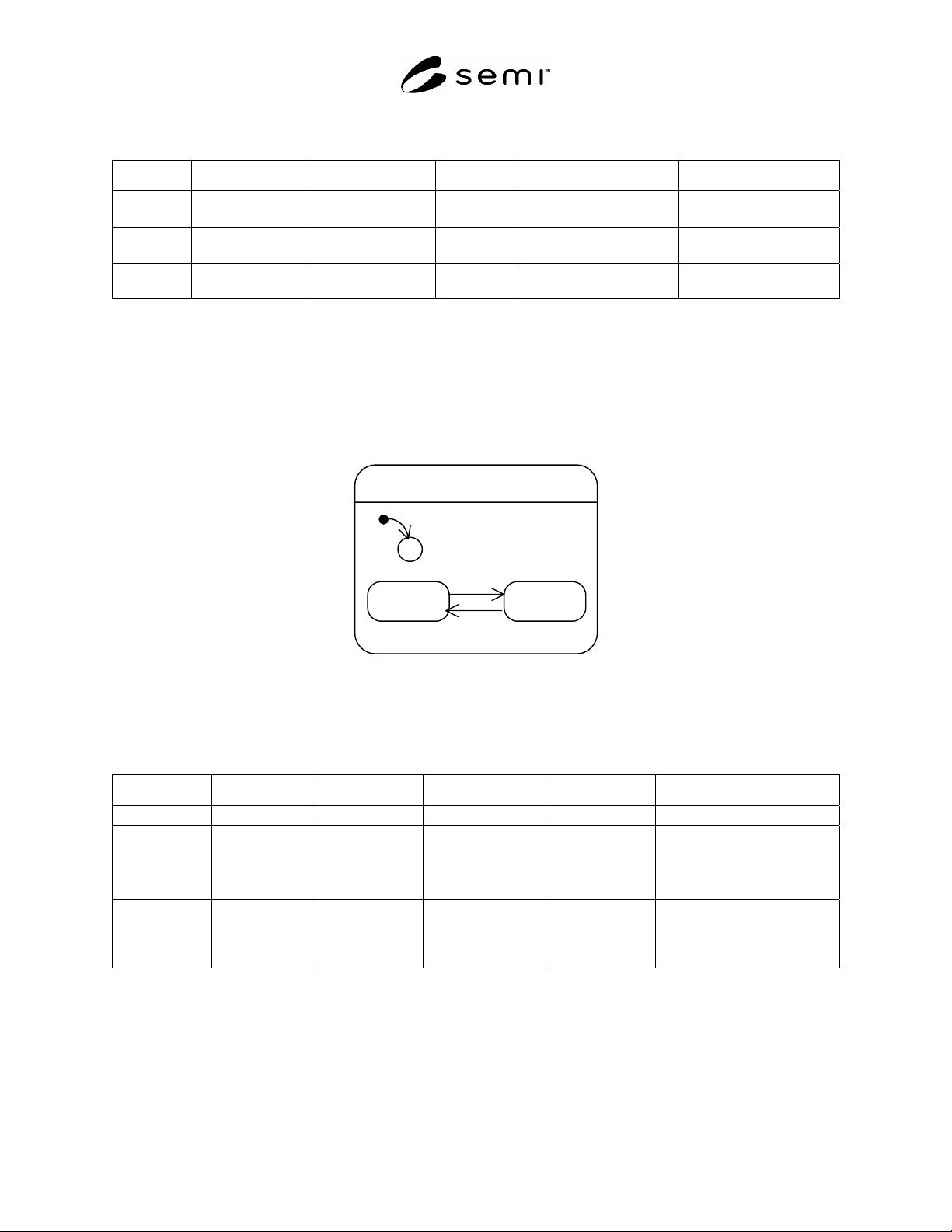
9.4.3.1 OP-Mode specifies the operation mode of the FPU. It can assume two values: Manual and Automatic. The
behavior of the FPU with respect to the states Manual and Automatic is out of scope.
Manual: FPU operates in manual mode.
Automatic: FPU operates in automatic mode.
OP-Mode
Manual Automatic
2
3
C
1
Figure 5
State Transition Diagram OP-Mode
Table 2 State Transition Table for OP-Mode
Number Previous State Trigger New State Actions Remark
1 (no state) Start up of FPU. Manual or Automatic None. Dependent on type of FPU.
2 Manual Trigger to switch
to Automatic.
Automatic FPU performs its
automatic
functions.
Trigger may be caused by:
manual operator action
or automatic trigger by a
programmed logic.
3 Automatic Trigger to switch
to Manual.
Manual FPU stops its
automatic
functions.
Trigger may be caused by:
manual operator action
or automatic trigger by a
programmed logic.
9.4.4 Control-Mode
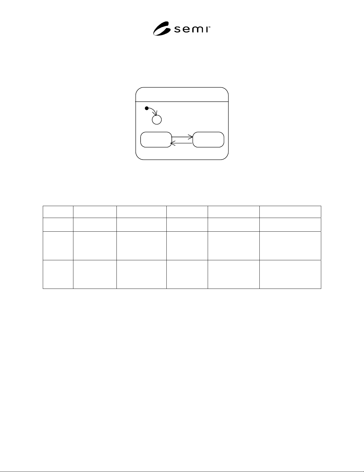
9.4.4.1 Control-Mode specifies the control mode of the FPU with respect to the FMCS. It may assume two values:
Local and Remote. The behavior of the FPU with respect to the states Local and Remote is out of scope. It is
dependent on the type of FPU. Control Mode is intended to be used by the FMCS to identify whether a remote
operation of the FPU is enabled or disabled – by this the FMCS can allow or disallow operator actions on the FMCS
SEMI F97-0305 © SEMI 2005 10
with respect to that particular FPU. On the FPU this control mode may be used to enable or disable remote control
of the FMCS.
Local: FPU operates in local mode, i.e. it can be controlled locally.
Remote: FPU operates in remote mode, i.e. it can be remotely controlled by the FMCS.
Control-Mode
Local Remote
2
3
C
1
Figure 6
State Transition Diagram Control-Mode
Table 3 State Transition Table Control-Mode
Number Previous State Trigger New State Actions Remark
1 (no state) Start up of FPU. Local or Remote FPU disables remote
control from FMCS.
Dependent on type of FPU.
2 Local Trigger to switch to
Remote.
Remote FPU enables remote
control from FMCS.
Trigger may be caused by:
manual operator action
or automatic trigger by a
programmed logic.
3 Remote Trigger to switch to
Local.
Local FPU disables remote
control from FMCS.
Trigger may be caused by:
manual operator action
or automatic trigger by a
programmed logic.
9.4.5 Run-Mode
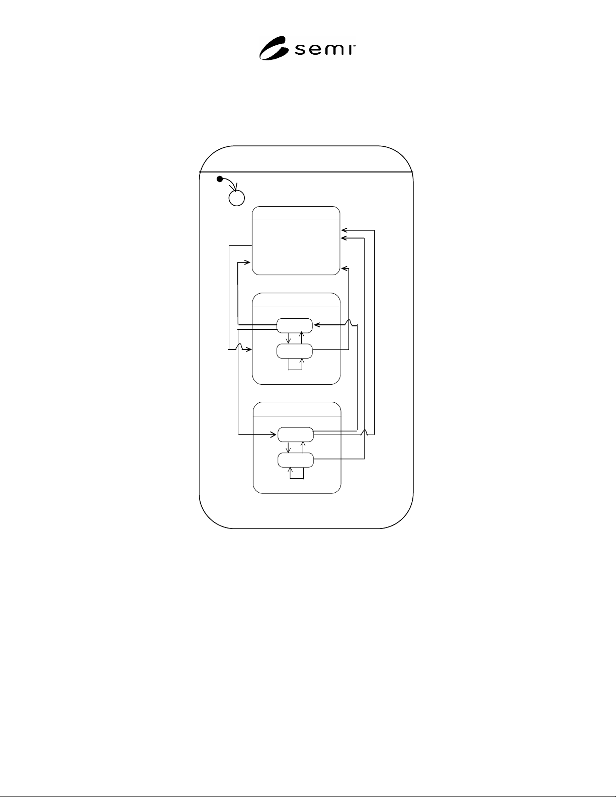
9.4.5.1 Run-Mode specifies the different running states of the FPU. It assumes three main values: Down, in Stand-
by or Run. The behavior of the FPU with respect to the states of Run-Mode is out of scope. It is dependent on the
type of FPU. The Annex to this Standard (see Related Information 1) provides some examples of the use of Run-
Mode. The Run-Mode provides general information of the FPU, whether it is Down, in Stand-by or in Run:
Down (the FPU is in a fault situation or it may be switched into Down by a pre scheduled function; this is
specified by an optional flag):
o flag set for scheduled down
o flag set for unscheduled down
Stand-by (the FPU is ready to be switched into Run).
Run (the FPU is running).
9.4.5.2 The FPU should assume optionally sub states when in Run or Stand-by. These sub states are:
Run: sub state Locked (the FPU is locked to hold the Run state) or Not_Locked and
Stand-by: sub state Locked (the FPU is locked to hold the Stand-by state) or Not_Locked.
SEMI F97-0305 © SEMI 2005 11
9.4.5.3 The locked sub state of Run and Stand-by may be used in order to force the FPU to maintain the current Run
or Stand-by state until the lock is disabled. The reasons causing the lock are out of scope of this standard. In
addition to the trigger to unlock, only critical failures can cause the FPU to leave the locked sub state. These critical
failures are being defined on a case by case basis by the purchaser and supplier of the FPU and the system
integrator.
Run-Mode
C
1
Run
Not_locked
Locked
10
12
11
14
Down
Stand-by
Not_locked
Locked
4
6
5
8
3
2
13
9
7
Figure 7
State Transition Diagram Run-Mode