semi合集-English.pdf - 第1336页
SEMI E30-1103 © SEMI 1992, 2003 10 NOT COMMUNICATING/EQUIPMENT-INITIATED CONNECT This state has two substates, WAIT CR A and WAIT DELAY. Upon any entry to the NOT COMMUNICATING state, whenever EQUIPMENT-INITIATED CONNECT…
SEMI E30-1103 © SEMI 1992, 2003
9
attempt to send S1,F13 shall occur only upon a
transit to the state WAIT CRA.
3.2.4 Communication States — There are two major
states of SECS communication, DISABLED and
ENABLED. The system default state must be user-
configurable at the equipment (e.g., via a jumper setting
or non-volatile memory variable).
Once system initialization has been achieved, the
opera-tor shall be able to change the communication
state selection at any time via equipment terminal
functions or momentary switch. A two-position type
switch must not be used due to possible conflict with
the system default.
The ENABLED state has two substates, NOT COM-
MUNICATING and COMMUNICATING, described
below. The equipment must inform the operator of the
current communication state via continuous display at
the equipment, including the NOT COMMUNI-
CATING and COMMUNICATING sub-states.
In the event of a connection transaction failure, a user-
configurable equipment constant EstablishCommunica-
tionsTimeout is used to establish the interval between
attempts to send an S1,F13 (Establish Communications
Request) while in the NOT COMMUNICATING sub-
state.
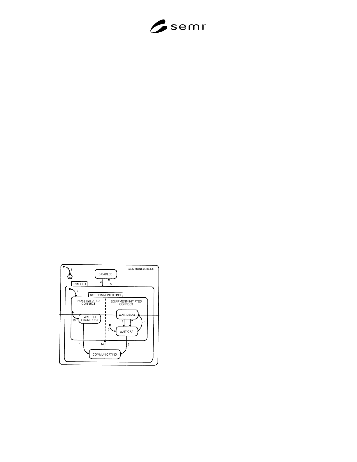
Figure 3.2.1 shows the relationship between the
superstates and substates of the Communications State
Model. A description of the events triggering state
transitions and the actions taken is given in Table 3.2.
Figure 3.2.1
Communications State Diagram
The states of the Communications State Model are
defined as follows:
DISABLED
In this state SECS-II communication with a host
computer is non-existent. If the operator switches
from ENABLED to DISABLED, all SECS-II
communications must cease immediately. Any
messages queued to send shall be discarded, and all
further action on any open transactions and
conversations shall be terminated.
4
Handling of
messages currently being transmitted is an issue for
lower level message transfer protocols and is not
addressed in this standard.
The DISABLED state is a possible system default.
ENABLED
ENABLED has two substates, COMMUNICA-
TING and NOT COMMUNICATING. Whenever
communications are enabled, either during system
initialization or through operator selection, the
substate of NOT COMMUNICATING is active
until communications are formally established.
Lower-level protocols (such as SECS-I) are
assumed to be functioning normally in that they are
capable of supporting the communication of SECS-
II syntax.
The ENABLED state is a possible system default.
ENABLED/NOT COMMUNICATING
No messages other than S1,F13, S1,F14, and S9,Fx
shall be sent while this substate is active. The
equipment shall discard any messages received
from the host other than S1,F13 or S1,F14
(Establish Communications Acknowledge). It shall
also periodically attempt to establish
communication with a host computer by issuing an
S1,F13 until communications are successfully
established. However, only one equipment-initiated
S1,F13 transaction may be open at any time.
The NOT COMMUNICATING state has two AND
substates, HOST-INITIATED CONNECT and
EQUIPMENT-INITIATED CONNECT, both of
which are active whenever the equipment is NOT
COMMUNICATING. These two substates clarify
the behavior of the equipment in the event that
both the equipment and the host attempt to
establish communications during the same period
of time
5
.
4 Refer to SEMI E5, Section 5, for definitions of SECS-II transaction
and conversation protocols.
5 Note that in the Harel notation, an exit from any AND substate is an
exit from the parent state and thus from all other AND substates of
that parent substate.

SEMI E30-1103 © SEMI 1992, 2003
10
NOT COMMUNICATING/EQUIPMENT-INITIATED
CONNECT
This state has two substates, WAIT CRA and
WAIT DELAY. Upon any entry to the NOT
COMMUNICATING state, whenever
EQUIPMENT-INITIATED CONNECT first
becomes active, a transition to WAIT CRA occurs,
the CommDelay timer is set to “expired,” and an
immediate attempt to send S1,F13 is made.
NOT COMMUNICATING/EQUIPMENT-INITIATED
CONNECT/WAIT CRA
An Establish Communications Request has been
sent. The equipment waits for the host to
acknowledge the request.
NOT COMMUNICATING/EQUIPMENT-INITIATED
CONNECT/WAIT DELAY
A connection transaction failure has occurred. The
CommDelay timer has been initialized. The
equipment waits for the timer to expire.
NOT COMMUNICATING/HOST-INITIATED CON-
NECT
This state describes the behavior of the equipment
in response to a host-initiated S1,F13 while NOT
COMMUNICATING is active.
NOT COMMUNICATING/HOST-INITIATED CON-
NECT/WAIT CR FROM HOST
The equipment waits for an S1,F13 from the host.
If an S1,F13 is received, the equipment attempts to
send an S1,F14 with COMMACK = 0.
ENABLED/COMMUNICATING
Communications have been established. The
equipment may receive any message from the host,
including S1,F13. When the equipment is
COMMUNICATING, SECS communications with
a host computer must be maintained. This state
remains active until communications are disabled
or a communication failure occurs. If the
equipment receives S1,F13 from the host while in
the COMMUNICATING substate, it should
respond with S1,F14 with COMMACK set to zero.
If the equipment receives S1,F14 from a previously
sent S1,F13, no action is required.
In the event of communication failure, the
equipment shall return to the NOT
COMMUNICATING substate and attempt to re-
establish communications with the host.
It is possible that the equipment may be waiting for
an S1,F14 from the host in EQUIPMENT-
INITIATED CONNECT/WAIT CRA at the time
an S1,F13 is received from the host in HOST-
INITIATED CONNECT/WAIT CR FROM HOST.
When this situation occurs, both equipment and
host have an open S1,F13/S1,F14 transaction.
Since communications are successfully established
on the successful completion of any S1,F13/S1,F14
transaction, either of these two transactions may be
the first to complete successfully and to cause the
transition from NOT COMMUNICATING state to
COMMUNICATING. In this event, the other
transaction shall remain open regardless of the
transition to COMMUNICATING until it is closed
in a normal manner.
If the equipment has not yet sent
6
an S1,F14 to a
previously received S1,F13 at the time when
COMMUNICATING becomes active, the S1,F14
response shall be sent in a normal manner. A
failure to send the S1,F14 is then treated as any
other communication failure.
If the equipment-initiated S1,F13/S1,F14 is still
open when the transition to COMMUNICATING
occurs, subsequent failure to receive a reply from
the host is considered a communication fault by
equipment. An S9,F9 should be sent when a
transaction timer timeout occurs
7
. (See Section 4.9
for definitions of communication faults and
message faults, as well as detail on Stream 9 Error
Messages.)
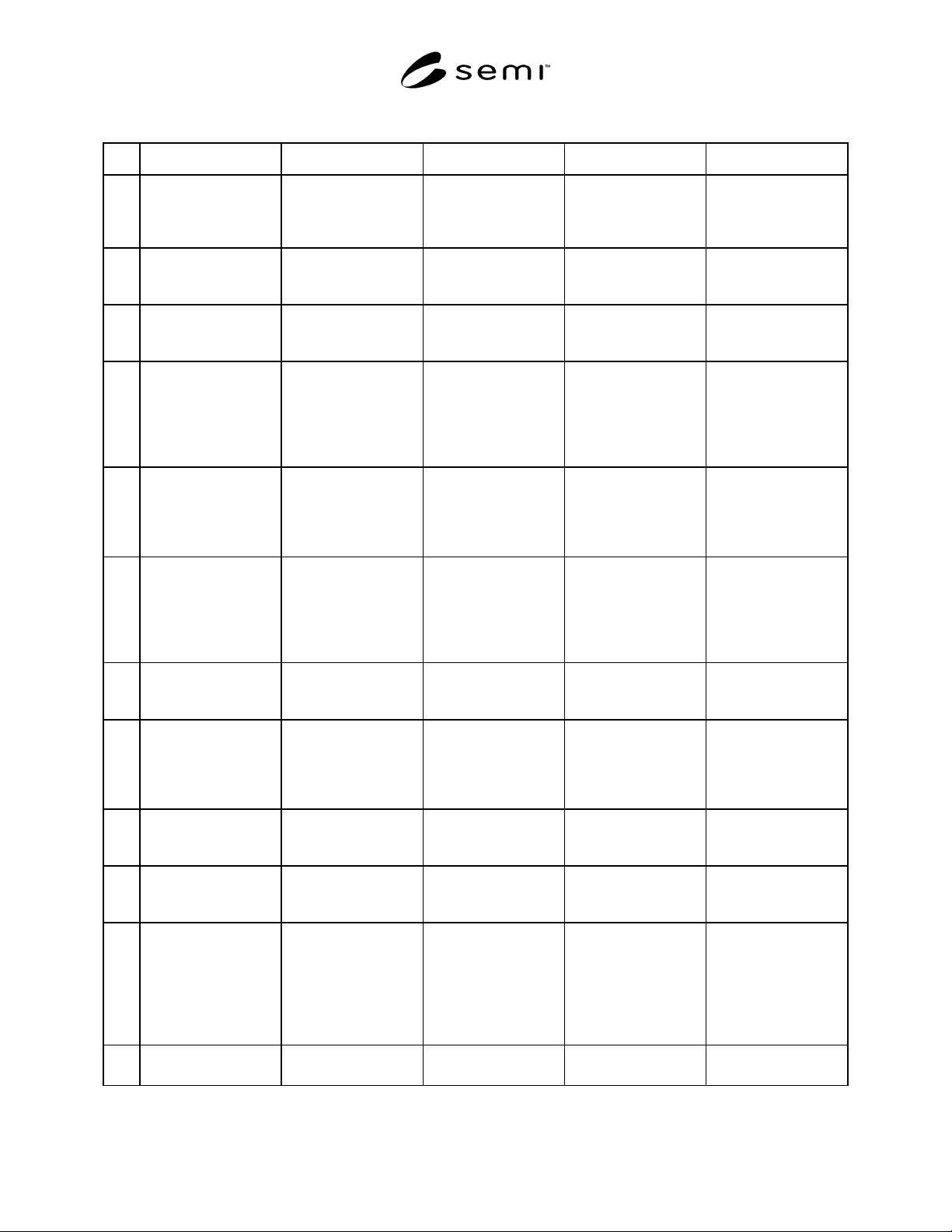
3.2.5 State Transitions — Table 3.2 contains a full
description of the state transitions depicted in Figure
3.2.1.
When the operator switches from the DISABLED state
to the ENABLED state, no collection event shall occur,
since no messages can be sent until communications
have been established. The process of establishing
communications serves to notify the host that
communications are ENABLED. No other collection
events are defined for the Communications State
Model.
6 This includes transmissions that may have started but not yet
successfully completed at the time that the transition to
COMMUNICATING occurs.
7 The existence of a transaction timer is not a requirement in some
protocols, such as SMS (SEMI E13).
SEMI E30-1103 © SEMI 1992, 2003
11
Table 3.2 Communications State Transition Table
# Current State Trigger New State Action Comment
1 (Entry to
COMMUNICA-
TIONS)
System initialization. System Default None. The system default
may be set to
DISABLED or
ENABLED.
2 DISABLED Operator switches
from DISABLED to
ENABLED.
ENABLED None. SECS-II
communications are
enabled.
3 ENABLED Operator switches
from ENABLED to
DISABLED.
DISABLED None. SECS-II
communications are
prohibited.
4 (Entry to
ENABLED)
Any entry to
ENABLED state.
NOT
COMMUNICATING
None. May enter from
system initialization
to ENABLED or
through operator
switch to
ENABLED.
5 (Entry to
EQUIPMENT-
INITIATED
CONNECT)
(Any entry to NOT
COMMUNICA-
TING)
WAIT CRA Initialize
communications. Set
CommDelay timer
“expired.” Send
S1,F13.
Begin the attempt to
establish
communications.
6 WAIT CRA Connection
transaction failure.
WAIT DELAY Initialize
CommDelay timer.
Dequeue all
messages queued to
send.
If appropriate,
dequeued messages
shall be placed in
spool buffer in the
order generated. Wait
for timer to expire.
7 WAIT DELAY CommDelay timer
expired.
WAIT CRA Send S1,F13 Wait for S1,F14.
May receive S1,F13
from Host.
8 WAIT DELAY Received a message
other than S1,F13.
WAIT CRA Discard message. No
reply. Set
CommDelay timer
“expired”. Send
S1,F13.
Indicates opportunity
to establish
communications.
9 WAIT CRA Received expected
S1,F14 with
COMMACK = 0.
COMMUNICATING None. Communications are
established.
10 (Entry to HOST-
INITIATED
CONNECT)
(Any entry to NOT
COMMUNICA-
TING)
WAIT CR FROM
HOST
None. Wait for S1,F13 from
Host.
14 COMMUNICATING Communication
failure. (See SEMI
E4 or SEMI E37 for
a protocol-specific
definition of
communication
failure.)
NOT
COMMUNICATING
Dequeue all
messages queued to
send.
Dequeued messages
may be placed in
spool buffer as
appropriate.
15 WAIT CR FROM
HOST
Received S1,F13. COMMUNICATING Send S1,F14 with
COMMACK = 0.
Communications are
established.