semi合集-English.pdf - 第645页
SEMI E84-0305 © SEMI 1999, 2005 43 No. Description of Passive Equipment HO_AVBL Signal Response 9 Manual Placement of a FOUP onto a Load Port in Auto Acces s Mode OFF 10 ES Signal OFF OFF #1 During normal load/unload ope…
SEMI E84-0305 © SEMI 1999, 2005 42
Interlock Signal
Signal Name P/A Description
PASS OK A->P
When this signal is HIGH
(ON), the vehicle may pass.
When this signal is LOW
(OFF), the vehicle may not
pass.
A1-4 Errors and Automated Recovery
A1-4.1 This section describes recommendations for implementation of errors and the associated recovery
procedures for Interbay OHS (Active Vehicle) and Intrabay OHT, definition of practical implementation of the
HO_AVBL and ES signals, and examples of various L_REQ and U_REQ sequences.
NOTE 6: This application note assumes an SEMI E84 implementation where one parallel I/O device per loadport is used.
A1-4.2 During the first few sequences of the SEMI E84 protocol before the carrier transfer begins if an error occurs
the active vehicle should send an error to the host but automatically recover without human intervention. The active
vehicle should automatically recover any SEMI E84 error up to the BUSY ON state.
A1-4.3
Definition of Automated Recovery — If an error occurs the active vehicle should send an Unsuccessful
Transfer Complete command to the HOST, then the HOST will send the active vehicle an alternate location. SEMI
E82 Intrabay SEM defines this recovery procedure in detail. Table A1-5 shows some specific scenarios where the
active vehicle should automatically recover.
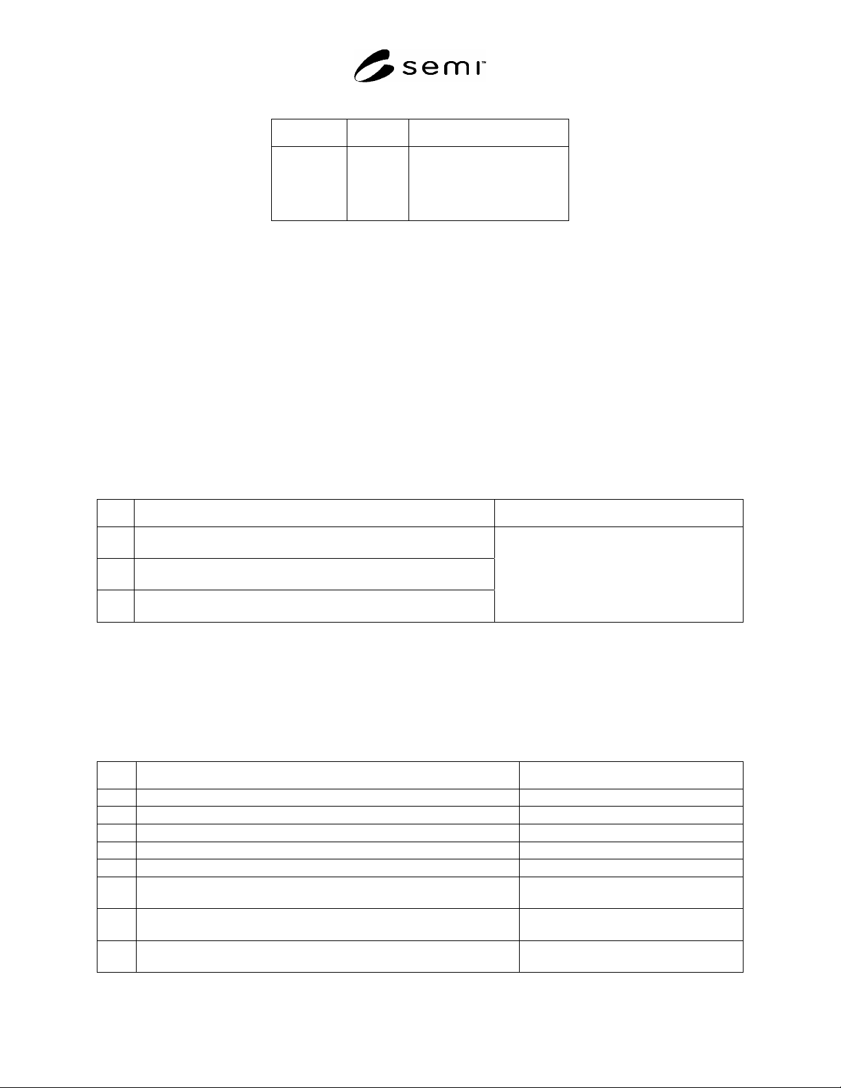
Table A1-5 Example Automatic Recover Scenarios
No. Error Description Active Equipment Reaction
1
TA1 Timeout: The active equipment sends the CS_0, CS_1 signal but
does not receive the U_REQ or L_REQ signal.
2
TA2 Timeout: The Active equipment sends the TR_REQ signal but
does not receive the READY signal.
3
During the sequence HO_AVBL signal goes low before BUSY turns
on.
Unsuccessful Transfer Complete is sent to the
Host and automatically recovered on the Active
side (no human intervention).
A1-4.4 HO_AVBL Signal
A1-4.4.1 The HO_AVBL signal specifies if the Passive Equipment is available to accept a Load / Unload from the
Active Equipment. The HO_AVBL should also be used to identify situations where harm to the carrier or product
may exist. The HO_AVBL signals are loadport specific and should not apply to all of the loadports on the
equipment. Table A1-6 shows some specific scenarios for the HO_AVBL Signal.
Table A1-6 Example HO_AVBL Scenarios
No. Description of Passive Equipment HO_AVBL Signal Response
1 Presence Sensor is ON but Placement sensor is OFF.
#1
OFF
2 Presence Sensor is OFF but Placement sensor is ON.
#1
OFF
3 Passive Equipment is in Manual Access Mode. OFF
4 FOUP is docked or moved forward to FIMS interface. OFF
5 Carrier present on the Input Port (internal buffer equipment or stocker). OFF
6
Light Curtain Errors on SEMI E15.1 Option 1 Loadports (Reference ¶7.6.1
of SEMI E15.1).
OFF
7
Light Curtain Errors on SEMI E15.1 non-automated Option 3 Loadports
(Reference ¶7.6.3 of SEMI E15.1).
ON
8
Carrier Handling Robot Errors not at the Active Carrier’s destination
loadport.
ON
SEMI E84-0305 © SEMI 1999, 2005 43
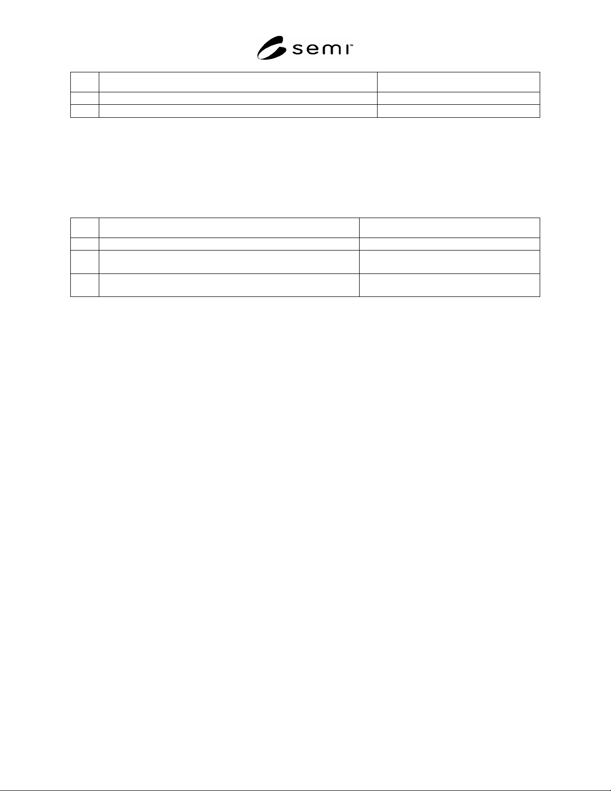
No. Description of Passive Equipment HO_AVBL Signal Response
9 Manual Placement of a FOUP onto a Load Port in Auto Access Mode OFF
10 ES Signal OFF OFF
#1
During normal load/unload operation the presence and placement sensors may turn on/off for a very short period.
A1-4.5 ES Signal
A1-4.5.1 The ES signal allows the Passive Equipment to signify to the Active Equipment any specific instance
where the material, product, or operation is in jeopardy. The ES Signal is not loadport specific but rather tool
specific. That means, for example, if an EMO is pressed on the Passive Equipment the ES signal should be OFF on
all SEMI E84 loadports. Table A1-7 shows some specific scenarios for the ES Signal.
Table A1-7 Example ES Signal Scenarios
No. Description ES Signal Response
1 EMO button is pressed. OFF
2
Interlocked maintenance door or interlocked panel on the Passive
Equipment is opened
OFF
3
Carrier Handling Robot is in Error at the load port (internal buffer
equipment or stocker)
OFF
A1-4.6 L_REQ and U_REQ Signals
A1-4.6.1 When the L_REQ and U_REQ signals are turned OFF they verify the completion of the Load/Unload
sequence as indicated by the presence/placement sensors on the load port.
A1-4.6.1.1
Here are some practical examples of using these signals.
1) During a Load both Presence and Placement sensors are ON once the carrier is detected. This should signal the
L_REQ signal to turn OFF. The L_REQ signal should typically not turn OFF unless both the presence and
placement sensors are ON.
2) When delivering, the Active Equipment should not release the FOUP until L_REQ is OFF.
3) During an Unload both Presence and Placement sensors are OFF once the carrier is not detected. This should
signal the U_REQ signal to turn OFF. The U_REQ signal should typically not turn OFF unless both the presence
and placement sensors are OFF.
4) The L_REQ and U_REQ signals should turn off immediately after the presence and placement sensors have
turned ON (load) or OFF (unload). There should be no delay timer between the presence and placement sensor
ON/OFF and L_REQ / U_REQ OFF.
5) During an Unload, once the active vehicle has fully gripped the FOUP, in most cases the vehicle should ignore
the response from the U_REQ signal until completion of its move. For example, the OHT vehicle should not stop
150 mm – 300 mm above the loadport, check the status of U_REQ and then complete its move. The OHT should
fully complete its move, check U_REQ and finish the E84 sequence. If the U_REQ signal is still high after the
completion of its move and the active vehicle can be certain the carrier is safely and securely contained aboard the
vehicle, in some cases the vehicle should abort the E84 sequence and continue normally to its destination.
A1-4.7
Error Messages
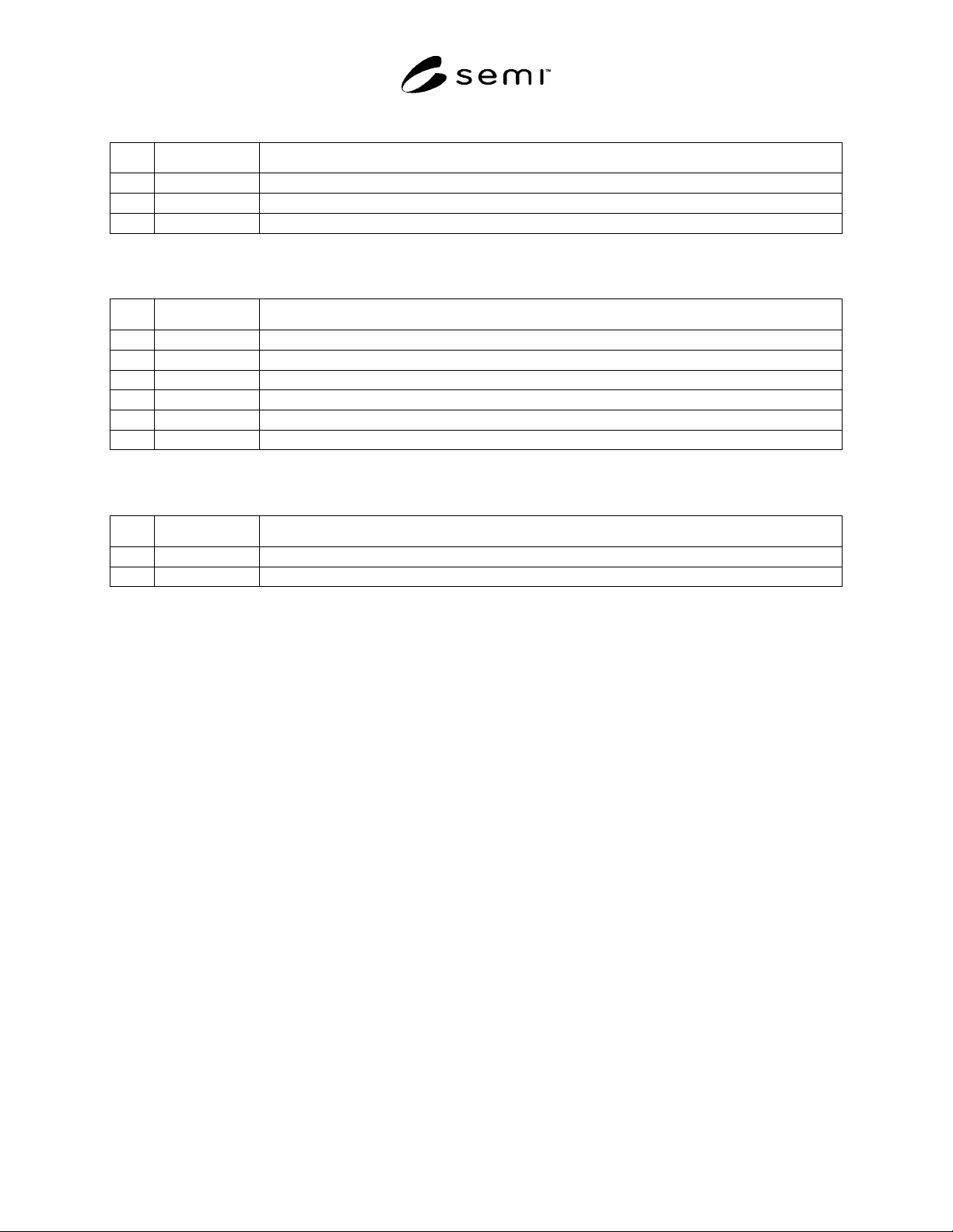
A1-4.7.1 Interlock timeouts are required to detect handoff sequence errors between the active and passive
equipment. When these timeouts occur, an error message shall be displayed to the user including the following
information: Timer Name, Timer Description, and current Timer setting. Some examples of error messages are
listed in Tables A1-8, A1-9, and A1-10.
SEMI E84-0305 © SEMI 1999, 2005 44
Table A1-8 Example Active Equipment Error Messages
No. Timer Name Equipment Error Message
1 TA1 TA1 Timeout – L_REQ/U_REQ signal did not turn ON within specified time. (TA1 = xxx)
2 TA2 TA2 Timeout – READY signal did not turn ON within specified time. (TA2 = xxx)
3 TA3 TA3 Timeout – READY signal did not turn OFF within specified time. (TA3 = xxx)
#1
“xxx” refers to the time in seconds that the specific timer was set to.
Table A1-9 Example Passive Equipment Error Messages
No. Timer Name Equipment Error Message
1 TP1 TP1 Timeout – TR_REQ signal did not turn ON within specified time. (TP1 = xxx)
2 TP2 TP2 Timeout – BUSY signal did not turn ON within specified time. (TP2 = xxx)
3 TP3 TP3 Timeout – Carrier was not detected/removed within specified time. (TP3 = xxx)
4 TP4 TP4 Timeout – BUSY signal did not turn OFF within specified time. (TP4 = xxx)
5 TP5 TP5 Timeout – VALID signal did not turn OFF within specified time. (TP5 = xxx)
6 TP6 TP6 Timeout – VALID signal did not turn ON within specified time. (TP6 = xxx)
#1
“xxx” refers to the time in seconds that the specific timer was set to.
Table A1-10 Example Delay Timer Error Messages
No. Timer Name Equipment Error Message
1 TD0 TD0 Timeout – VALID signal did not turn ON within specified time. (TD0 = xxx)
2 TD1 TD1 Timeout – VALID signal did not turn ON within specified time. (TD1 = xxx)
#1
“xxx” refers to the time in seconds that the specific timer was set to.
NOTICE: SEMI makes no warranties or representations as to the suitability of the standards set forth herein for any
particular application. The determination of the suitability of the standard is solely the responsibility of the user.
Users are cautioned to refer to manufacturer’s instructions, product labels, product data sheets, and other relevant
literature respecting any materials mentioned herein. These standards are subject to change without notice.
The user’s attention is called to the possibility that some implementations of this standard may involve use of
inventions covered by U.S. patents 4,306,292 and other patents issued or pending, held by Texas Instruments
Incorporated. By publication of this standard, SEMI takes no position respecting either the applicability or the
validity of these or other patent rights asserted in connection with any item mentioned in this standard. Users of this
standard are expressly advised that determination of any such patent rights, and the risk of infringement of such
rights, are entirely their own responsibility.
Copyright by SEMI® (Semiconductor Equipment and Materials
International), 3081 Zanker Road, San Jose, CA 95134. Reproduction of
the contents in whole or in part is forbidden without express written
consent of SEMI.