semi合集-English.pdf - 第2023页
SEMI E54.8-0305 © SEMI 1999, 2005 5 6.1.1 Message transf er is organize d in cycles. A message cycle m a inly consis ts of a reque st-frame followed by a corresponding ack nowledge/response-fr ame of the addressed statio…
SEMI E54.8-0305 © SEMI 1999, 2005 4
5.3 Terminology Mapping
5.3.1 As this standard defines the mapping of CDM data structure and behavior over a network, it makes use of
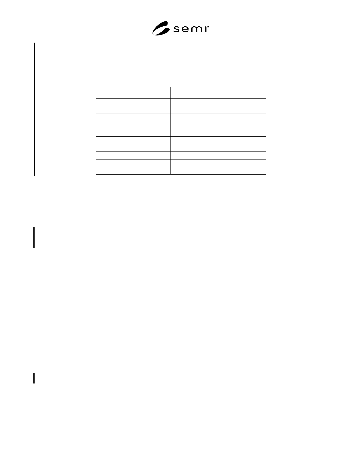
many of the terms in SEMI E54.1. Table 1 provides a mapping of fundamental terminology of the CDM document
into this document which uses the terminology of PROFIBUS.
Table 1 Mapping of CDM to NCS Terminology
CDM Term NCS Equivalent
Device DP Slave
Object = (with ASE as class specification)
Instance =
Attribute =
Behavior =
Service =
State Diagram Protocol Machine, State Machine
Byte =, Unsigned8
Nibble Specific field coding
Character String Visible String
5.4 Terminology Defined in PROFIBUS
5.4.1 Device Data Base — an electronic file that provides a clear and comprehensive description of the
characteristics of a device type in a precisely defined format. Also called a GSD File.
5.4.2 Device Profile — a Device Data Base Sheet, which specifies the characteristic features of a device, and a
GSD File.
5.4.3 Data Link Mapping Protocol Machine — a protocol layer that provides an interface to the Application Layer
Protocol Machines by translating service requests and responses between the Application Layer and the Fieldbus
Data Link.
5.4.4 DP-Master Class 1 (DPM1) — a device that polls its assigned DP-Slave devices and handles user data
exchange.
5.4.5 DP-Master Class 2 (DPM2) — a device that interacts as a configuration or diagnostic tool; usually a
programming device.
5.4.6 DP-Slave — a device that is configured, managed, and polled by Master devices; a DP-Slave initiates no
unsolicited communications.
5.4.7 Fieldbus Data Link — the PROFIBUS-DP model for the OSI Layer 2 definition.
5.4.8 GSD File — see Device Data Base.
5.4.9 Service Access Point — an addressable location in a device for the directing of service requests.
5.4.10 Send Data with No acknowledge — a service request that sends data with no reply.
5.4.11 Send and Request Data with reply — a service request that sends data followed by a reply by the receiving
device.
5.4.12 Slave Diagnostics — a method of retrieving a specifically formatted Data Structure that represents the
diagnostic status of a DP-Slave.
6 Communication Protocol High Level Structure
6.1 In a typical remote I/O configuration, single master architectures are used to optimize response times. In lower
speed applications, multi-master architectures are also possible. PROFIBUS-DP uses the polling principle for
communication (Master-Slave method).

SEMI E54.8-0305 © SEMI 1999, 2005 5
6.1.1 Message transfer is organized in cycles. A message cycle mainly consists of a request-frame followed by a
corresponding acknowledge/response-frame of the addressed station. An exception to this is the global-control
function for synchronization and coordination of several remote I/O stations.
6.1.2 A brief description of the PROFIBUS-DP protocol as it relates to the ISO 7498 OSI model follows in the
sections below. For protocol efficiency, PROFIBUS-DP does not define layers 3 to 6. Layer 7 is the interface
between the Application Process and the communication stack.
NOTE 1: The information contained in this section is for reference only. It in no way represents specifications for PROFIBUS-
DP. See related documentation for these specifications.
6.2 Physical Layer — Layer 1
6.2.1 There are three options specified for the Physical Layer (PHY): Manchester Coded Interface for Bus Powered
Systems, RS-485 and Optical. See the PROFIBUS-DP standard for more information about these options.
6.3 Data Link Layer — Layer 2
6.3.1 Data Transfer
6.3.1.1 The Data Link Layer or Fieldbus Data Link (FDL) provides the functions for sending and receiving data
over the network. Protocol Data Units (PDU) are packaged, delivered, and checked. Acknowledgements,
responses, retries, and timeouts are used to guard against Line Protocol Errors (e.g., frame, overrun, and parity) and
Transmission Protocol Errors (e.g., start and end delimiters, frame check, frame length, and response times).
6.3.1.2 A PDU is restricted to 246 bytes. In addition to the PDU, a transmission frame of variable length will
contain 8 bytes of overhead; one of fixed length (8 bytes) will contain 6 bytes of overhead. Various
acknowledgement and response frames are also defined.
6.3.1.3 To better understand the FDL, a summary of FDL data transfer services is given by the following list:
Send Data with Acknowledge (SDA),
Send Data with No Acknowledge (SDN), and
Send and Request Data with Reply (SRD).
6.4 Application Layer — Layer 7
6.4.1 The PROFIBUS application layer is structured in a so called service definition and protocol specification.
The service definition uses an object orientated approach and specifies the services for remote access and local
functions together with their objects (the ASE is a class definition of these objects). The protocol specification
includes both coding and state machines.
6.4.2 Service Definition
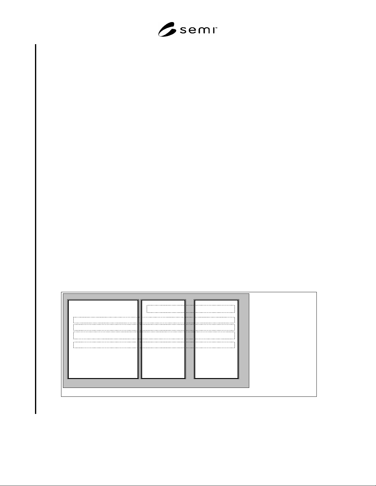
6.4.2.1 Application layer services are structured to reflect the needs of flexible configurable automation devices. A
Device consists of a set of modules that are placed in slots (see Figure 2). Modules are addressed uniquely by the
slot number. The module view can be a hardware oriented or reflects the software structure of the DP-Slave.
6.4.3 Slot 0 is used to address the DP Slave itself. Subslot 0 represents the module and contains no IO Data. The
other object classes can have instances scattered over the modules addressed by slot number. Each module can
contain IO Data, Context parameter, Diagnosis information, Process Data and Alarms. Process Data is a generic
class which can contain different application specific parameters accessible by read and write services. There is a
set of identification and maintenance parameters defined in a PROFIBUS Guideline.
6.4.3.1 Object classes are defined for:
IO Data for periodic reporting,
Context for configuration,
Diagnosis for event collection,
Process Data for polled access, and
Alarms for asynchronous event reporting.
SEMI E54.8-0305 © SEMI 1999, 2005 6
6.4.3.1.1 A set of services are defined for these object classes.
6.4.3.2 IO Data is handled mainly by buffered services which allow decoupling between application and
communication. Client/Server service structure (request/response) is used for Record Data, Context and Diagnosis.
6.4.4 Protocol Specification
6.4.4.1 A DP-Slave shall get a FDL address before using it in the target configuration.
6.4.4.2 To access a DP-Slave the DP-Master has to check the availability with a Slave-Diag service. To establish
the context a SetPrm service is issued first. A check is done to ensure that the appropriate device type with the
required resources is accessed. The following ChkCfg service. Another Slave Diag service has been used to check
the establishment of the application relationship.
6.4.4.3 After this start up procedure the data exchange of IO data can be done and alarms can be signaled from the
DP Slave to the DP Master. The DP Master can invoke services to read and write process data that contain all kind
of information e.g. produced units, calibration information, and batch information.
6.4.4.4 A context is monitored by the Data Exchange Service at the DP-Slave. The DP-Master monitors the
communication by the receipt of the responses to the FDL services.
6.4.5 Data Link Mapping Protocol Machine (DMPM)
6.4.5.1 The DMPM performs the interpretation of service requests from, and responses to, the Application Protocol
Machines. Table 2 is included to demonstrate the basic structure of the PROFIBUS-DP DMPM. For speed and
efficiency, the PROFIBUS-DP protocol defines the Service Access Point (SAP). These are included in the
transmission protocol to direct messages within the device for fast dedicated processing. Defined are Destination
SAP (DSAP) and Source SAP (SSAP).
6.4.6 I&M Functions
6.4.6.1 “Identification & Maintenance Functions” (I&M functions) define general parameters and protocols. The
main purpose of the I&M functions is to support the end user during various scenarios of a device’s life cycle be it
configuration, commissioning, parameterization, diagnosis, repair, firmware update, asset management, audit
trailing, and alike. Well-defined uniform parameters and rules should enable the manufacturers to offer devices that
behave in a uniform manner These profile guidelines take into account requirements from FDA (Food & Drug
Administration) and others. The basic information offered can be characterized as “Type Plate” or “Boiler Plate”. It
consists of Manufacturer ID, Order ID, Serial Number, Hardware Revision, Software Revision, Revision Counter,
and Profile ID.
DP Slave
...
Slot0
Slot 1 carries
M o dule x
...
Record Data
Diagnosis
Alarm
IO Data
Context
Slot n carries
Module y
Figure 1
Device Model