semi合集-English.pdf - 第453页
SEMI E66-1103 © SEMI 1997, 2003 2 5.1.11 psig — pounds per square i n ch gauge 5.1.12 Ra — roughne ss average per ANSI B 46.1 5.1.13 RH — relative humidity per ANSI B46.1 5.1.14 Rmax — roughness maximum 5.1.15 scfm — sta…

SEMI E66-1103 © SEMI 1997, 2003 1
SEMI E66-1103
TEST METHOD FOR DETERMINING PARTICLE CONTRIBUTION BY
MASS FLOW CONTROLLERS
This test method was technically approved by the Global Gases Committee and is the direct responsibility of
the North American Gases Committee. Current edition approved by the North American Regional Standards
Committee on July 27, 2003. Initially available at www.semi.org October 2003; to be published November
2003. Originally published September 1997.
1 Purpose
1.1 The purpose of this test is to measure particle
contribution by mass flow controllers (MFCs) in high-
purity gas systems.
2 Scope
2.1 This document describes a test method that yields
statistically significant comparisons of particle
contribution among mass flow controllers under test
conditions.
NOTICE: This standard does not purport to address
safety issues, if any, associated with its use. It is the
responsibility of the users of this standard to establish
appropriate safety and health practices and determine
the applicability of regulatory or other limitations prior
to use.
3 Limitations
3.1 This document is not intended as a method for
monitoring in situ particulate performance once a
particular MFC has been tested.
3.2 The test medium is limited to nitrogen. Actual
performance under normal operating conditions may
differ.
3.3 The accuracy of the data generated by this method
is limited to the accuracy of the particle measuring
instruments used.
3.4 This test method is intended for use by operators
who understand the use of the apparatus at a level
equivalent to one year of experience.
3.5 This test method should not be expected to yield
comparable results from one test set up to another, due
to the limitations of current particle counting
technology.
3.6 Results may be compromised by the methods used
to construct the apparatus.
4 Referenced Standards
4.1 SEMI Standards
SEMI E29 — Standard Terminology for the Calibration
of Mass Flow Controllers and Mass Flow Meters
SEMI F1 — Specification for Leak Integrity of High-
Purity Gas Piping Systems and Components
4.2 ANSI Standards
1
ANSI B46.1 — Surface Texture (Surface Roughness,
Waviness, and Lay)
4.3 ISO Standards
2
ISO 14644-1 — Cleanrooms and associated controlled
environments Part 1: Classification of air cleanliness.
ISO 14644-2 — Cleanrooms and associated controlled
environments Part 2: Specifications for testing and
monitoring to prove continued compliance with ISO
14644-1
NOTICE: Unless otherwise indicated, all documents
cited shall be the latest published versions.
5 Terminology
5.1 Abbreviations and Acronyms
5.1.1 CNC — condensation nucleus counter
5.1.2 dof — degrees of freedom
5.1.3 DUT — device under test
5.1.4 FS — full scale
5.1.5 IKS — isokinetic sampler
5.1.6 kPa — kiloPascal
5.1.7 LPC — laser particle counter
5.1.8 ppm — parts per million
5.1.9 psia — pounds per square inch absolute
5.1.10 psid — pounds per square inch differential
1 American National Standards Institute, Headquarters: 1819 L
Street, NW, Washington, DC 20036, USA. Telephone: 202.293.8020;
Fax: 202.293.9287, New York Office: 11 West 42nd Street, New
York, NY 10036, USA. Telephone: 212.642.4900; Fax:
212.398.0023, Website: www.ansi.org
2 International Organization for Standardization
ISO Central Secretariat, 1, rue de Varembé, Case postale 56, CH-
1211 Geneva 20, Switzerland. Telephone: 41.22.749.01.11; Fax:
41.22.733.34.30 Website: www.iso.ch
SEMI E66-1103 © SEMI 1997, 2003 2
5.1.11 psig — pounds per square inch gauge
5.1.12 Ra — roughness average per ANSI B46.1
5.1.13 RH — relative humidity per ANSI B46.1
5.1.14 Rmax — roughness maximum
5.1.15 scfm — standard cubic feet per meter
5.1.16 SFC — supply mass flow controller
5.1.17 slpm — standard liters per minute
5.1.18 SPC — statistical process control
5.2 Definitions
5.2.1 background counts — Counts contributed by the
test apparatus (including counter electrical noise) with
the spool piece in place of the test object.
5.2.2 condensation nucleus counter (CNC) — A light
scattering instrument that detects particles in a gaseous
stream by condensing supersaturated vapor on the
particles.
5.2.3 dynamic control mode test — A test performed to
determine particle contribution as a result of test flow
variation within the normal range of MFC operation
(i.e., 0 to 100% flow).
5.2.4 impact or vibration test — A test performed to
determine particle contribution as a result of test flow
variation within the normal range of MFC operation
(i.e., 10 to 100% flow).
5.2.5 normal statistical distribution — Measurements
that randomly fall about an average, within a range of ±
3 standard deviations.
5.2.6 observation — A 10-minute sample/data
collection period.
5.2.7 purge mode — Control valve fully open.
5.2.8 sample flow — The volumetric flow drawn by the
counter for particle detection.
5.2.9 sampling time — The time increment over which
counts are recorded.
5.2.10 spool piece — A null component consisting of a
straight piece of electropolished tubing and appropriate
fittings used in place of the test component to establish
the background.
5.2.11 stable particle level — Particle level that has
been consistent, as described in Appendix 1, for at least
eight consecutive readings.
5.2.12 standard reference conditions — 101.32 kPa,
0.0°C (14.7 psia, 32°F) (see SEMI E29)
5.2.13 statistical process control — A method used by
this standard for analyzing experimental data that
follows a normal statistical distribution to determine if
the test is stable.
5.2.14 steady state control mode test — A test
performed to determine particle contribution during
steady state test flow within the normal operating range
of the MFC (i.e., 10 to 100% full scale).
5.2.15 supply pressure — Pressure immediately
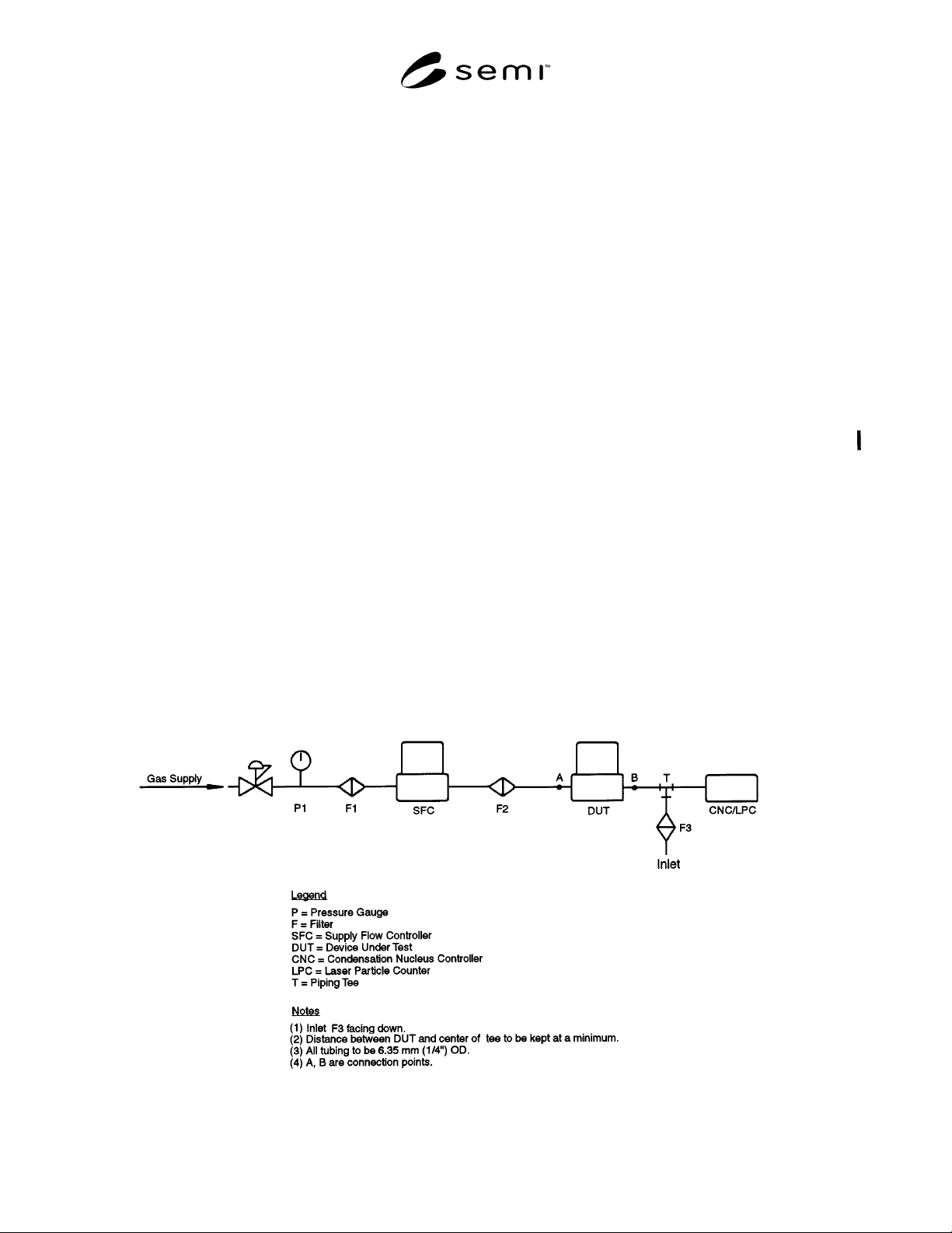
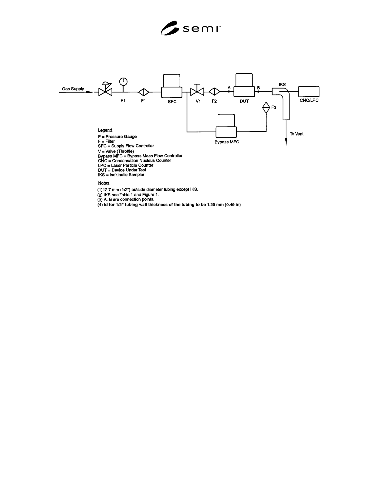
upstream of filter F1. (See Figures 1 and 2.)
5.2.16 test flow — Mass flow through the device under
test.
SEMI E66-1103 © SEMI 1997, 2003 3
Figure 1
Test Set-Up when Test Flow < Sample Flow
Figure 2
Test Set-Up when Test Flow > Sample Flow
6 Summary of Test Method
6.1 Background count is determined for steady state
control, dynamic control, and impact tests. The steady
state control mode test, dynamic control mode test, and
impact test are run by counting particles for the time
necessary to achieve a stable particle level. Background
testing is performed again.
7 Significance and Use
7.1 The significance of this test method is that it
defines a procedure for testing mass flow controllers
intended for installation into a high-purity gas system.
It is intended for use by manufacturers and end users.
8 Apparatus
8.1 Test Gas — Nitrogen of minimum dryness, with -
40°C (-40°F) dew point at 790.57 kPa (100 psig) and
with < 10 ppm of total hydrocarbons.
8.2 Membrane Filters — To provide filtered test gas,
nine-log retentive to larger than 0.01 mm particles, with
a pressure drop of less than 7.91 kPa (1 psid) at 283,170
sccm (10 scfm) for a 790.57 kPa (100 psig) inlet, and
capable of achieving less than one particle
3
0.01 mm
per cubic foot of test gas under test conditions.
8.3 Pressure Regulator — Made of electropolished
316L stainless steel, with an internal surface finish of
0.18 mm (7 µin.) R
a
and 0.25 mm (10 µin.) Rmax, to
maintain system test pressure.
8.4 Pressure Gauge or Transducer — Made of
electropolished 316L stainless steel, with an internal
surface finish of 0.18 mm (7 µin.) R
a
and 0.25 mm (10
µin.) Rmax, to monitor system test pressure.
8.5 Throttle Valve — Made of electropolished 316L
stainless steel, with an internal surface finish of 0.18
mm (7 µin.) R
a
and 0.25 mm (10 µin.) Rmax, to
proportion flow in test system.
8.6 Tubing — Made of electropolished 316L stainless
steel, with an internal surface finish of 0.18 mm (7 µin.)
Ra and 0.25 mm (10 µin.) Rmax.
8.7 Supply Flow Controller (SFC) — Metal-sealed,
used to establish a flow rate through the spool piece in
the absence of the DUT, with a settling time less than or
equal to that of the DUT. More than one range SFC
may be required to run all the tests.
8.8 Sampler — Constructed according to the drawing
and design parameters shown in Figure 3 and Table 1,
to collect gas from the stream exiting the test device,
where the sample is near-isokinetic in design.
8.9 Upstream Adapter — To connect 12.7 mm (1/2 in.)
tubing to the test device. For 12.7 mm (1/2 in.) test
devices, the adapter is a simple face-seal connector. For
6.35 mm (1/4 in.) test devices, the adapter is a tapered