semi合集-English.pdf - 第7142页
SEMI S22-1103a © SEMI 2003, 2005 27 17.5 Multi-Outlet Assemblies Multi-outlet power assemblies should: a) contain receptacles suitable for c ommerc ial or industrial application, and b) be a min imu m si ze o f 70 mm (…
SEMI S22-1103a © SEMI 2003, 2005 26
17.1.2 The installation of flexible conduits and cables should be such that liquids drain away from the fittings.
17.1.3 Terminal blocks should be mounted and wired so that the internal and external wiring does not cross over the
terminals.
17.1.4 Conductors and cables should be connected from terminal to terminal without splices.
17.1.5 Where circuits operate at different voltages, the conductors of each voltage level should be separated by
suitable barriers, or routed separately and secured, or all conductors grouped or bundled together should be insulated
for the highest voltage present in the group or bundle.
17.1.6 Conductors smaller than 1/0 AWG should not be connected in parallel to the same terminations to attain the
necessary ampacity.
17.1.7 Conductors should not be exposed to temperatures greater than their temperature rating. If the wire
termination has a lower temperature rating than the conductor, the lower temperature rating should be used to
evaluate the suitability of the conductor.
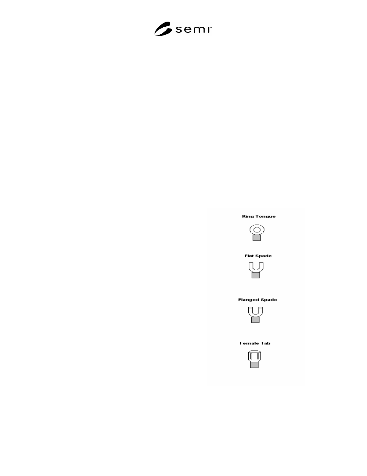
17.2 Terminal Lugs Terminal lugs should be utilized according to the following:
a) Ring Tongue Desired for all terminations not routinely disconnected for access and service;
b) Flat Spade not desired for terminating hazardous potentials or hazardous energy levels and not suitable for
bonding or earthing (grounding).
c) Flanged Spade not desired for earthing except on a captive screw;
d) Female Tab
Desired only for terminations to fixed male tabs on components or panels.
17.3 Attachment Plugs, Cord Connectors, and
Receptacles If an unacceptable risk can result from
misconnection, then receptacles and cord connectors
should not accept an attachment plug with a different
voltage or current rating.
17.3.1 Only female cord connectors should be used to
supply power.
17.3.2 Receptacles should be rated for at least 125
percent of the maximum rated design load (current)
intended for the circuit.
17.3.3 Each receptacle should be individually bonded
to the protective earthing system.
17.3.4 Series connection of the protective conductor
from receptacle to receptacle should not be used.
17.3.5 Convenience receptacles accessible from the
exterior of the equipment should be protected by a
ground-fault circuit-interrupter (GFCI).
NOTE 47: A receptacle that is used to supply power to a
subsystem is not a convenience receptacle.
17.4 Temporary Power Taps Temporary power taps
(commercial power strips) should not be used for
installation in or on equipment.
EXCEPTION: Permanently installed fixed power strips
that are suitable for industrial equipment are acceptable
if they have been evaluated by an accredited testing
laboratory for this application.
Figure 1
Terminal Lugs

SEMI S22-1103a © SEMI 2003, 2005 27
17.5 Multi-Outlet Assemblies Multi-outlet power assemblies should:
a) contain receptacles suitable for commercial or industrial application, and
b) be a minimum size of 70 mm (2.75 in.) by 36.6 mm (1.44 in).
17.6 Identification of Conductors
17.6.1 Each conductor should be identified by a number, letter, color, a combination of the above or other scheme
consistent with the product documentation.
17.6.2 Where color is used for the sole means of identification, it is acceptable to apply appropriate colored tape or
sleeve at the conductor ends. The tape or sleeve should be wrapped around, or otherwise reliably secured to, the
conductor.
17.6.3 Identification of the Protective Conductor Electrical wiring for protective conductors should be labeled
for easy identification at both ends of the wire. The protective conductor should be readily distinguishable by shape,
location, marking, or color.
17.6.3.1 When color alone is used to identify the protective conductor, the bicolor combination green and yellow
should be used throughout the length of the conductor. The bicolor combination green and yellow should be such
that on any 15 mm length, one of the colors covers at least 30 percent and not more than 70 percent of the surface of
the conductor with the other color covering the remainder of the surface.
EXCEPTION: Solid green can be used to identify protective conductors if the documentation describes this means
of identifying protective earth.
17.6.3.2 Green and yellow or green alone should not be used to identify any other conductor.
17.6.4 Identification of the Earthed (Neutral) Conductor Where color alone is used to identify the earthed
(neutral) conductor, white or gray should be used.
EXCEPTION: Light blue will be acceptable if the earthed (neutral) conductor is identified by an additional means.
NOTE 48: Light blue may not be accepted in some jurisdictions.
17.6.4.1 White, gray, and light blue should not be used to identify any other conductors.
17.6.5 Identification of Other Conductors Where color alone is used to identify other conductors, black should
be used for all unearthed AC and DC power circuits.
17.7 Wiring Inside Electrical Enclosures
17.7.1 Wiring that carries hazardous voltage located inside enclosures should be securely routed to avoid
mechanical abuse during maintenance or troubleshooting.
17.7.2 Wiring should be protected from contact with liquids that may be present under reasonably foreseeable
single fault conditions, unless the wiring is suitably rated for a wet environment.
17.7.3 Wires should be routed away from sharp edges or surfaces that may degrade their insulation.
17.7.4 Wire guides may be used for wire routing. However, these guides should be constructed so as not to
adversely affect the insulation of the wires they secure.
17.8 Wiring Outside Electrical Enclosures
17.8.1 Conductors external to the electrical enclosure(s) should be enclosed in suitable ducts, raceways, or run in
suitable multi-conductor cable. Fittings used with ducts, raceways, or multi-conductor cable should be suitable for
the anticipated physical environment. Cables should not be subjected to physical stress (e.g. pinching, crushing, foot
traffic, or abrasion).
17.8.2 Flexible conduit or flexible multi-conductor cable should be used where it is necessary to employ flexible
connections to pendant push-actuator stations. The weight of the pendant stations should be supported by means
other than the flexible conduit or the flexible multi-conductor cable, except where the conduit or cable is specifically
designed for that purpose.

SEMI S22-1103a © SEMI 2003, 2005 28
17.8.3 Cables that exit an electrical enclosure should be provided with adequate strain relief to ensure a mechanical
pull cannot dislodge the cable’s termination points. Compliance is verified by conducting a strain relief test in
accordance with ¶22.7 Strain Relief Test.
17.8.4 Flexible cables installed in or on machines should be protected to avoid insulation breakdown due to normal
operating conditions, single fault conditions, or foreseeable misuse. Some of the factors that should be considered
are:
a) moving machine parts,
b) brackets or cable guides on the machine,
c) abrasion,
d) exposure to liquids and gas,
e) exposure to radiation, and
f) temperature deviations.
NOTE 49: Natural rubber can be degraded by chemicals normally present in semiconductor fabrication facilities.
17.8.5 Where cables are subject to movement or are routed close to moving parts, precautions should be taken to
maintain a space of at least 25 mm (1 inch) between the moving parts and the cables. Where that distance is not
practicable, fixed barriers should be provided between the cables and the moving parts.
17.8.6 Where flexible conduit is adjacent to moving parts, the construction and supporting means should satisfy the
following:
a) It should prevent damage to the flexible conduit under normal operating conditions.
b) It should prevent damage to the insulation on the wire inside the conduit under single fault conditions.
17.8.7 Plug/Receptacle Combinations Where equipment is portable, connections to it should be made through a
polarized plug/receptacle combination.
17.8.8 Field wiring terminals connected at the time of installation should meet the wire bending space criteria in
Appendix 1, Tables A1-1 through A1-5.
EXCEPTION: Equipment that meets the wire bending space requirements of NFPA 70 will also meet these criteria.
17.8.9 Ducts and Connection Boxes
17.8.9.1 General Cables used in ducts should be suitably rated.
17.8.9.2 Fill of Ducts and Raceways The total cross sectional area of conductors permitted in raceways and ducts
should not exceed 50 percent of the interior cross sectional area of the raceway or duct.
NOTE 50: All other limiting factors for wires and cables should be taken into account. For example, temperature limitations may
reduce the number of allowable conductors.
17.8.9.3 Conduit and Fittings Non-flexible and flexible conduit and fittings should be suitable for the anticipated
conditions of use. Conduits should be securely held in place and supported at each end.
17.8.9.4 Fittings should be compatible with the conduit and appropriate for the application.
17.8.9.5 Fittings should be secured by a means that requires a tool to remove.
17.8.9.6 Conduit bends should be made in such a manner that the conduit should not be damaged and the internal
diameter of the conduit should not be effectively reduced.
17.8.9.7 Connection Boxes Connection boxes should provide protection against the intrusion of substances that
may damage insulation or may cause ground-faults.
17.8.9.8 The size of the connection box should be sufficient to allow dissipation of heat generated during normal
operation.
17.9 Subsystem Interconnection — Conductors that are connected between subsystems at the time of installation
should have wire bending space in accordance with ¶9.3.4 and phase identification in accordance with ¶9.1.6.3.