semi合集-English.pdf - 第2307页
SEMI E82-0705 © SEMI 1999, 2005 3 5.1.9 PGV — Person Guided Vehicle 5.1.10 RGT — Rail Guided Transport 5.1.11 TCP/IP — Transm ission Communicati on Protocol/ Internet Protocol 5.1.12 TSC — T ransport Sy stem Controller 5…

SEMI E82-0705 © SEMI 1999, 2005 2
3.2.1.4 Automated Guided Transport (AGT) — A ground-based transport system with automated guidance (i.e., no
rail guidance). Automated guidance system allows vehicles to access SEMI E15.1 compliant ports.
3.2.1.5 Direct WIP Conveyer (DWC) — An overhead transport system, based on direct WIP roller conveyers. No
vehicles are used for point to point delivery. The conveyers are positioned for vertical access to SEMI E15.1 ports.
3.2.2 Transport vehicles may contain zero or more internal buffers for carrier transport. If mechanically feasible,
the transport system may acquire or deposit carriers simultaneously. If transported in a safe manner, carrier
transport may occur while occupying the acquire/deposit transfer port(s) of the transport vehicle (e.g., a single
position hoist vehicle). In the context of this standard, a “vehicle” on a DWC is defined as a single carrier in the
transport system.
3.3 Physical Layout Limitations
3.3.1 The equipment controlled by a single TSC must allow for a carrier to be transported from any given source
port to any destination port via a single transfer command without the assistance of an external device (manual or
automated). In other words, if a source port and a destination port are controlled by a TSC, there must not exist a
physical or logical barrier that prevents a carrier from being moved between the two ports. This assumes that the
type of carrier (FOUP, Reticle Pod, etc.) is permitted at the source and destination ports.
4 Referenced Standards
4.1 SEMI Standards
SEMI E4 — SEMI Equipment Communications Standard 1 Message Transfer (SECS-I)
SEMI E5 — SEMI Equipment Communications Standard 2 Message Content (SECS-II)
SEMI E23 — Specification for Cassette Transfer Parallel I/O Interface
SEMI E30 — Generic Model for Communications and Control of Manufacturing Equipment (GEM)
SEMI E32 — Material Movement Management (MMM)
SEMI E37 — High-Speed SECS Message Services (HSMS) Generic Services
SEMI E84 — Specification for Enhanced Carrier Handoff Parallel I/O Interface
4.2 Other References
Harel, D., “Statecharts: A Visual Formalism for Complex Systems,” Science of Computer Programming 8 (1987)
231-274.
1
NOTICE: Unless otherwise indicated, all documents cited shall be the latest published versions.
5 Terminology
5.1 Abbreviations and Acronyms
5.1.1 AGT — Automated Guided Transport
5.1.2 AMHS — Automated Material Handling System
5.1.3 DWC — Direct WIP Conveyor
5.1.4 FOUP — Front Opening Unified Pod
5.1.5 GEM — Generic Equipment Model
5.1.6 ITS — Interbay or Intrabay Transport System
5.1.7 OHS — Over Head Shuttle
5.1.8 OHT — Overhead Hoist Transport
1 Elsevier Science, P.O. Box 945, New York, NY 10159-0945, http://www.elsevier.nl/homepage/browse.htt

SEMI E82-0705 © SEMI 1999, 2005 3
5.1.9 PGV — Person Guided Vehicle
5.1.10 RGT — Rail Guided Transport
5.1.11 TCP/IP — Transmission Communication Protocol/ Internet Protocol
5.1.12 TSC — Transport System Controller
5.2 Definitions
5.2.1 active vehicle — a vehicle in the transport system that contains a robot or other transfer agent for providing
the acquiring (loading) and depositing (unloading) actions.
5.2.2 buffer — a set of one or more locations for holding carriers at the production equipment.
5.2.3 carrier — a container with one or more fixed positions for holding substrates. Examples of carriers include
FOUPs and open cassettes.
5.2.4 FOUP — a closed carrier for holding wafers.
5.2.5 host — the factory computer system, or an intermediate system, that represents the factory and the user to the
equipment. Refers to the system that controls or supervises the Transport System Controller (TSC) throughout this
document.
5.2.6 internal buffer — locations within the equipment to store carriers. These locations exclude load ports.
5.2.7 internal transfer port — a specific type of transfer port, which is internal to a single TSC domain. As an
example, this location may be used to transfer carriers among different vehicles in a single TSC domain.
5.2.8 load port — the interface location on the equipment where carriers are delivered.
5.2.9 open cassette — an open structure that holds one or more wafers.
5.2.10 passive vehicle — a vehicle in the transport system that does not contain a robot or other transfer agent for
providing the acquiring (loading) and depositing (unloading) actions. The vehicle simply contains a position(s) to
carry the transfer unit. The loading and unloading action must be accomplished at the load or unload port by a
different system (e.g., stocker port robot).
5.2.11 process equipment — equipment used to make semiconductor devices. This excludes metrology and
material handling equipment.
5.2.12 production equipment — equipment used to produce semiconductor devices, including wafer sorting,
process, and metrology equipment and excluding material handling equipment.
5.2.13 transfer port — point on the transport system at which a change of equipment ownership of the carrier
occurs. See also internal transfer port.
5.2.14 transfer unit — the element of movement (assemblage of carriers) of the ITS that consists of a maximum
number of carriers allowed in a specific transfer command:
AA is the maximum number of carriers allowed for acquire at the transfer source.
BB is the maximum number of carriers allowed for deposit at the transfer destination.
CC is the maximum number of carriers allowed for transfer in one transport vehicle.
The maximum size of the transfer unit is the minimum of AA, BB, and CC.
5.2.15 Transport System — a transport system dedicated to one or more bays in the factory and responsible for
transferring carriers to production equipment, from production equipment, from production equipment to production
equipment or from stocker to stocker. TS consists of the physical units of the system (e.g., vehicles, nodes, docking
stations), the low-level unit controllers, and a system-level controller. TS excludes factory floor storage systems
(stockers), but includes any short-term storage integral to the system, such as storage locations within an overhead
track system that are accessible only to units of the particular TS.
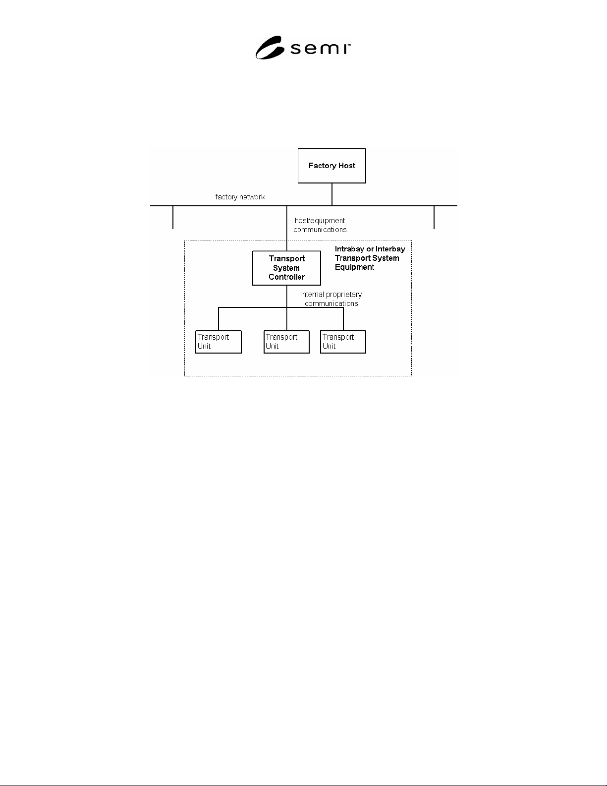
5.2.16 Transport System Controller — interbay or intrabay Transport System Controller that communicates with
the Factory Host and represents the system as the equipment.
SEMI E82-0705 © SEMI 1999, 2005 4
5.2.17 Transport System Equipment — an individual transport system viewed as a single piece of equipment, with
distributed components and distributed control. The TS controller communicates with the host using HSMS and
GEM and represents the system as an equipment. The factory may require more than one type of transport system.
5.2.18 transport unit — a physical component of a transport system, such as a vehicle, node, or docking unit.
Figure 1
Example of Transport System Equipment
6 Communication Requirements
6.1 It is required that any IBSEM compliant equipment follow the Communications State Model in SEMI E30. In
addition, IBSEM compliant equipment shall support either the High-speed SECS Message Services Single-Session
Mode (SEMI E37 and SEMI E37.1, HSMS and HSMS-SS) communication standard or SEMI Equipment
Communications Standard 1 Message Transfer (SEMI E4, SECS-I) communication standard.
7 State Models
7.1 State Model Requirements
7.1.1 The state models included in this standard are a requirement for IBSEM equipment. This standard requires
implementation of all SEMI E30 state models (such as control, communication, on-line/off-line, etc. according to
the GEM capabilities required per §13). A state model consists of a state model diagram, state definitions, and a
state transition table. All state transitions in this standard, unless otherwise specified, shall correspond to collection
events.
7.1.2 A state model is the host’s view of the equipment, and does not necessarily describe the internal equipment
operation. All IBSEM state model transitions shall be mapped into the appropriate internal equipment events that
satisfy the requirements of those transitions. In certain implementations, the equipment may enter a state and have
already satisfied all of the conditions required by the IBSEM state model for transition to another state. The
equipment makes the required transition without any additional actions in this situation.
7.1.3 Some equipment may need to include additional substates other than those in this standard. Additional
substates may be added, but shall not change the IBSEM defined state transitions. All expected transitions between
IBSEM states shall occur.