semi合集-English.pdf - 第6552页
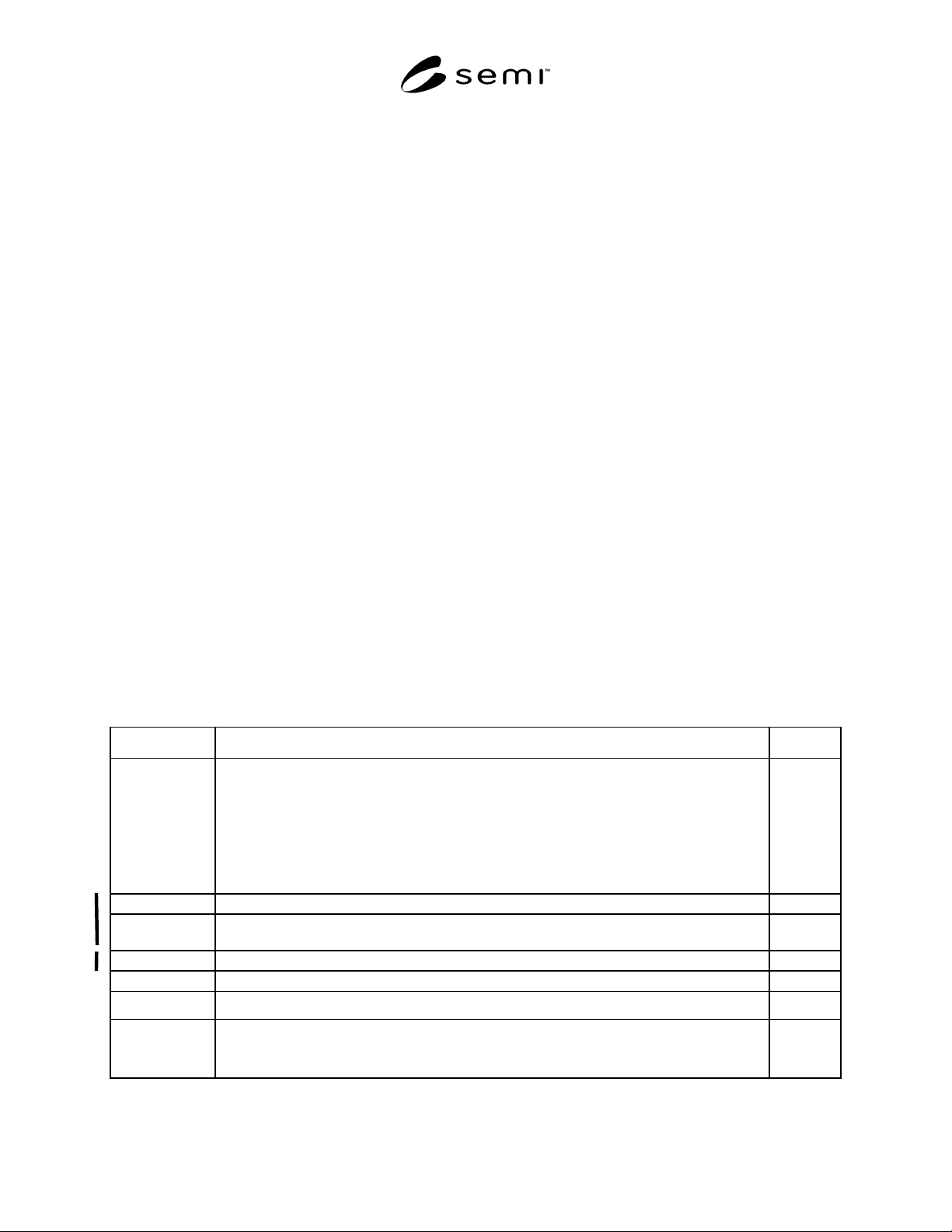
SEMI G84-0303 © SEMI 2001, 2003 2 7.1.1 A — ASCII charact er(s), m ay not be re quired terminal charact er such as null (0 0 16 ) 7.1.2 B — Binary 7.1.3 I — Integer num ber 7.1.4 U — Unsigned Integer number 7.1.5 Li st o…

SEMI G84-0303 © SEMI 2001, 2003 1
SEMI G84-0303
SPECIFICATION FOR STRIP MAP PROTOCOL
This specification was technically approved by the Global Automated Test Equipment Committee and is the
direct responsibility of the North American Automated Test Equipment Committee. Current edition approved
by the North American Regional Standards Committee on October 25, 2002 and November 22, 2002.
Initially available at www.semi.org January 2003; to be published March 2003. Originally published
November 2001.
1 Purpose
1.1 The purpose of this specification is to provide
definition that will enable the implementation of strip
mapping throughout the assembly and test process. This
document will enable standardization of the strip map
format and execution method throughout the factory
floor.
1.2 This document describes the format and methods in
which strip map information shall be formatted and
used to transfer information about a strip to and from
equipment using the SECS/GEM interface standard (see
SEMI E5).
2 Scope
2.1 This specification will identify the messages within
the SECS/GEM message set used in the implementation
of strip mapping.
2.2 This specification will identify the Map Data Items
(MDI) that are required or optionally may be used in
the implementation of strip mapping.
2.3 This document will provide basic application notes
to aid in the proper implementation of strip mapping.
2.4 This document will not address application or
implementation for wafer test process.
NOTICE: This standard does not purport to address
safety issues, if any, associated with its use. It is the
responsibility of the users of this standard to establish
appropriate safety and health practices and determine
the applicability of regulatory or other limitations prior
to use.
3 Limitations
3.1 This document does not address the transmission,
file naming conventions, storage or archiving of strip
maps.
4 Referenced Standards
4.1 SEMI Standards
SEMI E5 — SEMI Equipment Communications
Standard 2 Message Content (SECS-II)
SEMI G81
— Specification for Map Data Items
SEMI T9 — Specification for Marking of Metal Lead-
Frame Strips with a Two-Dimensional Data Matrix
Symbol
NOTICE: Unless otherwise indicated, all documents
cited shall be the latest published versions.
5 Terminology
5.1 Definitions
5.1.1 assembly site — the sub-contractor, supplier’s
facility or department that will be responsible for the
assembly of IC devices.
5.1.2 bottom-side — the bottom of the strip as defined
by the customer based on the customer master
manufacturing drawing.
5.1.3 cell — a term used to represent the mapping item
on a strip—unit, package, device, multi-chip module,
etc.
5.1.4 strip — a leadframe, board, panel or other
container which hold locations for semiconductor
devices to be manufactured upon.
5.1.5 strip map — a record of data in a file that
contains quality and historical information about each
individual strip in a manufacturers lot.
5.1.6 substrate — a board or panel containing locations
for semiconductor devices to be manufactured upon.
Also referred to as strip, board or PCB.
5.1.7 supplier — a supplier of inspected/tested
substrates (strips) and strip maps to the assembly site.
5.1.8 top-side — the top of the strip as defined by the
customer based on the customer master manufacturing
drawing.
6 Ordering Information
None.
7 Convention
7.1 The following conventions are used to represent
data format. Each format is represented by an
alphabetic character and optional data size given by
“byte” unit. Exceptions are “*” and “List of”. Refer to
SEMI E5 for details.
SEMI G84-0303 © SEMI 2001, 2003 2
7.1.1 A — ASCII character(s), may not be required terminal character such as null (00
16
)
7.1.2 B — Binary
7.1.3 I — Integer number
7.1.4 U — Unsigned Integer number
7.1.5 List of — Combined item format consisting of one or more items; array (items of the same type) or structure
(items of different types)
7.1.6 * — Any format as above or those allowed in SEMI E5.
8 Object Definitions
8.1 The implementation of Strip Mapping defines one standard object, the Strip Map.
8.1.1 Strip Map Object Definition — The Strip Map is a dynamic object created and modified through the
assembly and test process. Each Strip Map Object is a logical representation of a manufacturing lead frame or
substrate and maintains the current processing state for the group of die attached to that physical leadframe or
substrate. Each Strip Map Object uniquely identifies a manufacturing leadframe or substrate using the ObjID
(StripID) object attribute. The object attribute notation used in Table 1 is described in Conventions, Section 7.
9 Requirements
9.1 Equipment Communication
9.1.1 Communication of strip maps between host and equipment shall use the SECS I or HSMS protocols.
Otherwise, some other general protocols, which are widespread in the data communication field, could be used as an
alternative. However, these are not covered in this specification.
9.2 Map Data Items
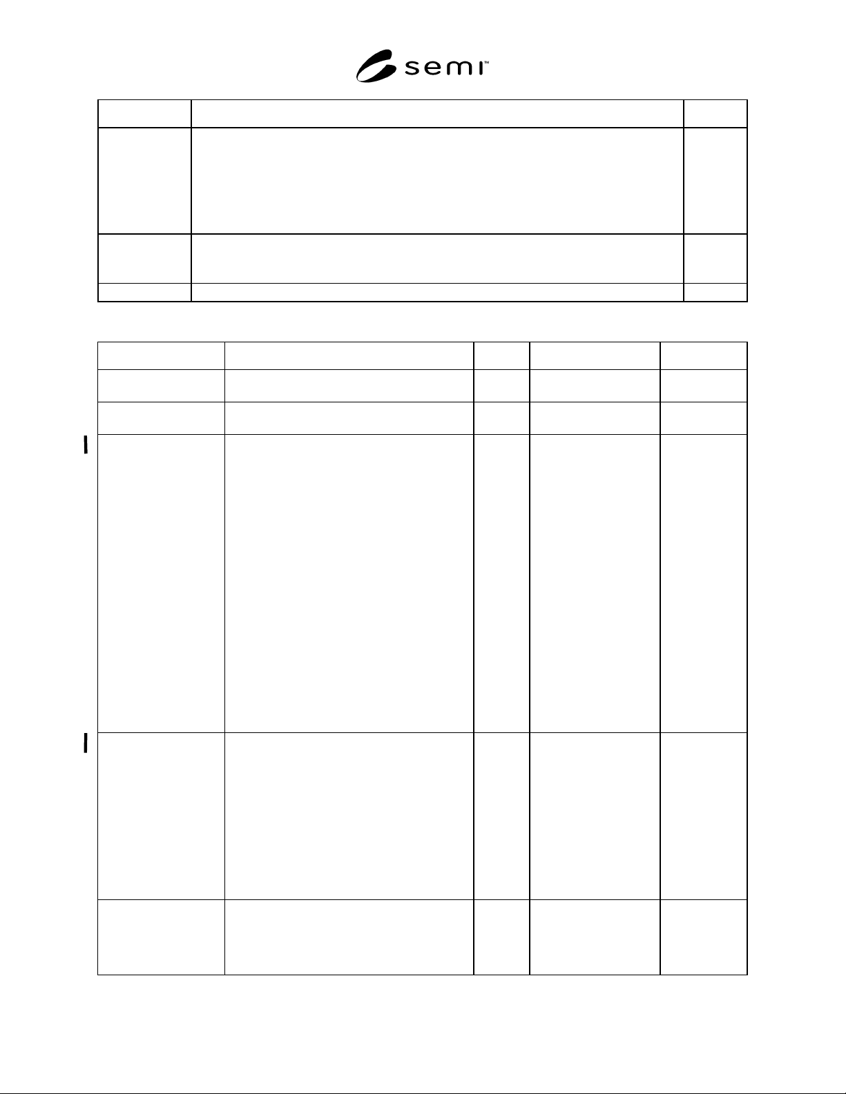
9.2.1 The Standard Map Data Items in Table 1 contain the standard data items that shall be used in all strip mapping
implementations.
9.2.2 The Strip Map Data Items in Table 2 are the data items and object attributes that will be used in the
implementation of strip mapping via the SECS/GEM interface as needed by each equipment type and process step.
Table 1 Standard Data Item/Object Description and Settings
Data Item Description / Settings Format
SMORLOC 0 = Error
1 = Upper right
2 = Upper left
3 = Lower left
4 = Lower right
> 4 = Error
5-63 Reserved
U1
ERRCODE Code identifying an error U2
ERRTEXT Text string describing the error noted in the corresponding ERRCODE. Limited to 80
characters maximum.
A
OBJACK Acknowledge Code U1
ATTRID Object attribute ID A
ATTRDATA Object attribute data *
ACKC6 Strip map acknowledge
0 = successful
1 = failed
B
SEMI G84-0303 © SEMI 2001, 2003 3
Data Item Description / Settings Format
OBJSPEC A text string that has an internal format and that is used to point to a specific object instance.
The string is formed out of a sequence of formatted substrings, each specifying an object’s type
and identifier. The substring format has the following four fields: object type, colon character
“:”, object identifier, greater than symbol “>”, where the “:” is used to terminate an object type
and the “>” is used to terminate an identifier field. The object type may be omitted where it
may be otherwise determined. The final “>” is optional.
The OBJSPEC for the StripMap Object is a zero-length item. No specifier required.
A
OBJTYPE Identifier for a group or class of objects. All objects of this type must have the same set of
attributes.
Available object types: “StripMap”
A
OBJID Object Identifier A
Table 2 Strip Map Data Item/Object Description and Settings
Attribute Name Definition Access Required Format
ObjType The object type, “StripMap” RO Y A =
“StripMap”
ObjID The object. This is the StripID, FrameID or
equivalent.
RO Y A
CellStatus Cell Status is an array of values indicating the
value of each unit/package/device on a strip.
0 = Functional Good Cell; Good die placed on
Good cell.
1 = Unknown Cell Status.
2 = Defect/Non-functional Cell; the cell is
marked as defect by previous steps.
CellStatus shall be sent in an array of size
Rows × Columns in row major format with
respect to the OriginLocation.
CellStatus may be provided by the host to the
equipment as well as from the equipment to
the host.
Used in: Strip Map Upload and Strip Map
Download
RW Y’
Either CellStatus or
CellGrade or both are
required if mapping is
to be used.
U1
CellGrade CellGrade is an array of values indicating the
classification of each unit/package/device/cell
on a strip. The process and equipment using a
‘grading’ scheme determine this classification
and the associated values. Examples of a
CellGrade are test bins, sort grades, package
grade, marking grades etc.
CellGrade shall be sent in an array of size
Rows × Columns in row major format with
respect to the OriginLocation.
RW Y’
Either CellStatus or
CellGrade or both are
required if mapping is
to be used.
U1
Columns The number of columns of (measured) device
matrix on substrate, that is the number of
devices on the X-axis of the map data. It is
required if the type of the map data is simple
array structure.
RO Y U4