semi合集-English.pdf - 第871页
SEMI E116-0705 © SEMI 2002, 2005 3 5 Terminology 5.1 Abbrevi ations and Acrony ms 5.1.1 EFEM — Equi pment Front End Module 5.1.2 EPT — Equipment Performance Tracking 5.1.3 GEM — Generic Equipm ent Model [SEM I E30] 5.2 D…

SEMI E116-0705 © SEMI 2002, 2005 2
2.3 This standard specifies the concepts, behavior, and message services that enable the host computer to obtain the
equipment data required for equipment performance tracking in an automated and consistent manner, without
operator or host input. It does not specify the report of SEMI E10 states from the equipment to a host computer, as
this information requires user input and is already specified by SEMI E58.
2.4 This standard does not conflict with SEMI E58 nor does it inhibit the equipment’s ability to report out SEMI
E10 states via SEMI E58.
2.5 This standard is a building block towards SEMI E10 and SEMI E79 by providing accurate equipment
information required for SEMI E10 and SEMI E79 metrics, without dependence on operator or host input,
eliminating inaccuracies due to incorrect or untimely input from the user. EPT assists both SEMI E10 and SEMI
E79 by providing a modular approach to equipment performance tracking, allowing the state of the equipment to be
determined by the states of its major modules. EPT assists SEMI E79 by providing task-level detail of the
equipment or module’s current activity, allowing performance metrics to be tracked at the task level.
2.6 This is a provisional standard. In order to have the provisional status removed, the following areas must be
completed:
Equipment Interlock Information
Equipment Process Monitoring Information
Equipment Maintenance Trigger Information
Application of EPT State Model to load ports and internal buffers
NOTICE: This standard does not purport to address safety issues, if any, associated with its use. It is the
responsibility of the users of this standard to establish appropriate safety and health practices and determine the
applicability of regulatory or other limitations prior to use.
3 Limitations
3.1 This standard applies to semiconductor production equipment. Other types of equipment have not been
examined. However, it may be used for other types of equipment when applicable.
4 Referenced Standards and Documents
4.1 SEMI Standards
SEMI E10 Specification for Definition and Measurement of Equipment Reliability, Availability, and
Maintainability (RAM)
SEMI E39 — Object Services Standard: Concepts, Behavior, and Services
SEMI E30 Generic Model for Communications and Control of Manufacturing Equipment (GEM)
SEMI E58 Automated Reliability, Availability, and Maintainability Standard (ARAMS): Concepts, Behavior,
and Services
SEMI E79 Standard for Definition and Measurement of Equipment Productivity
SEMI E90 Specification for Substrate Tracking
SEMI E98 Provisional Standard for the Object-Based Equipment Model (OBEM)
SEMI 101 Provisional Guide for EFEM Functional Structure Model
NOTICE: Unless otherwise indicated, all documents cited shall be the latest published versions.

SEMI E116-0705 © SEMI 2002, 2005 3
5 Terminology
5.1 Abbreviations and Acronyms
5.1.1 EFEM — Equipment Front End Module
5.1.2 EPT — Equipment Performance Tracking
5.1.3 GEM — Generic Equipment Model [SEMI E30]
5.2 Definitions
5.2.1 EPT module — a major component of the equipment that affects processing or throughput.
5.2.1.1 For purposes of simplification, an EPT module executes one and only one task at a time. Each EPT Module
has an EPT state model that is maintained by the equipment.
5.2.2 EPT state — the state of IDLE, BUSY, or BLOCKED within EPT state model.
5.2.3 event report — a message the equipment sends to the host on the occurrence of a collection event.
5.2.4 fault — an exception.
5.2.5 host — the factory computer system or an intermediate system that represents the factory and the operator to
the equipment.
5.2.6 intended function — a manufacturing function that the equipment was built to perform. This includes
transport functions for transport equipment, measurement functions for metrology equipment, as well as process
functions such as physical vapor deposition and wire bonding. Complete equipment may have more than one
intended function. [SEMI E58]
5.2.7 material — the basic unit of process. For the purposes of this standard, material is a set of one or more
substrates.
5.2.8 module — a major component of equipment that contains at least one material location and performs some
task on material. Equipment modules may be aggregates of equipment subsystems, I/O devices, and other modules.
[SEMI E98]
5.2.9 substrate — the basic unit of material on which work is performed to create a product. Examples include
wafers, die, plates used for masks, flat panels, circuit boards, and leadframes. [SEMI E90]
5.2.10 task — a planned and repeatable activity with an expected duration and a definite beginning and end (e.g.,
Move wafer from cassette to stage, Pre-align wafer, Align reticle, Preheat chamber, Increase vacuum). NOTE:
Actual durations may vary.
5.2.11 trigger — an event that causes a change in the state of the equipment. Examples are changes in sensor
readings, alarms, and messages received from the host, and operator commands.
5.2.12 unit
any wafer, die, packaged device, or piece thereof (included product and non-product units). [SEMI
E10]
5.2.13 user — any entity interacting with the equipment, either locally as an operator or remotely via the host.
From the equipment’s viewpoint, both the operator and the host represent the user. [SEMI E58]
6 Requirements
6.1 An EPT compliant implementation requires provision of certain capabilities defined by other standards:
accessibility to status information, event reporting, alarm management, and provision of an internal time-and-date
clock. These requirements may be satisfied through compliance to SEMI E30 for the following sets of
requirements:
Clock Services
Event Notification
Status Data Collection
SEMI E116-0705 © SEMI 2002, 2005 4
Equipment Constants
Alarm Management
6.2 An EPT compliant implementation requires a documented list of all EPT modules contained within the
equipment.
6.3 An EPT compliant implementation requires an EPT state model for the equipment and for each EPT module.
6.4 Each EPT module shall have a documented list of tasks that the module may perform.
7 Conventions
7.1 This document follows the conventions for state model methodology and service definitions used by the SEMI
standards referenced in §4.
7.2 State Model Methodology
7.2.1 A state model has three elements: definitions of each state and sub-state, a diagram of the states showing the
valid transitions between states, and a corresponding state transition table that defines the triggers for each
transition. The diagram of the state model uses the Harel State Chart notation. An overview of this notation is
presented in an Appendix of SEMI E30. The definition of this notation is presented in Science of Computer
Programming 8, “Statecharts: A Visual Formalism for Complex Systems”, by D. Harel, 1987.
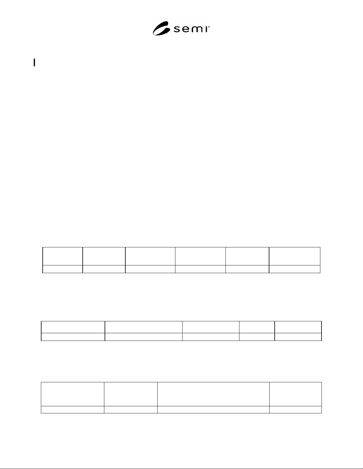
7.2.2 Transition tables are provided in conjunction with the state diagrams to explicitly describe the nature of each
state transition. A transition table contains columns for Transition number, Previous State, Trigger, New State,
Actions, and Comments. The “trigger” (column 3) for the transition occurs while in the “previous” state. The
“actions” (column 5) includes a combination of:
1) Actions taken upon exit of the previous state.
2) Actions taken upon entry of the new state.
3) Actions taken that are most closely associated with the transition.
7.2.3 No differentiation is made between these cases.
# PREVIOUS
STATE
TRIGGER NEW STATE ACTIONS COMMENTS
Transition #
7.3 Variable Data Item Definition
7.3.1 The variable item dictionary contained in this document defines the variable name, description, type (format),
access (read/write or read only), and comments about the variable. This is depicted in the format of the following
table:
VARIABLE NAME DESCRIPTION TYPE ACCESS COMMENT
7.4 Event Description
7.4.1 The collection event description table contained in this document includes the event name, the state model
transition, the description, and the data required for the event. This is depicted in the format of the following table:
EVENT NAME STATE MODEL
TRANSITION
NUMBER
DESCRIPTION REQUIRED DATA