semi合集-English.pdf - 第5451页
SEMI M60-0305 © SEMI 2005 19 Table R1-3 Temperature Dep endence. (Area = 1mm 2 , J = 0.1 A / cm 2 ) NOTICE: SEMI makes no warranties or represen tations as to the suitability o f the standards set forth herein for any pa…
SEMI M60-0305 © SEMI 2005 18
J
(A/cm
2
)
Failure (%)
Qbd (C/cm
2
)
at Weibull = 0
0.01 15.4 5.9
0.05 15.0 5.4
0.1 14.7 5.2
-5
-4
-3
-2
-1
0
1
2
3
1.E-02 1.E-01 1.E+00 1.E+01 1.E+02
Qbd (C/cm
2
)
Ln(-Ln(1-F))
10mA
10mA
10mA
50mA
50mA
50mA
100mA
100mA
100mA
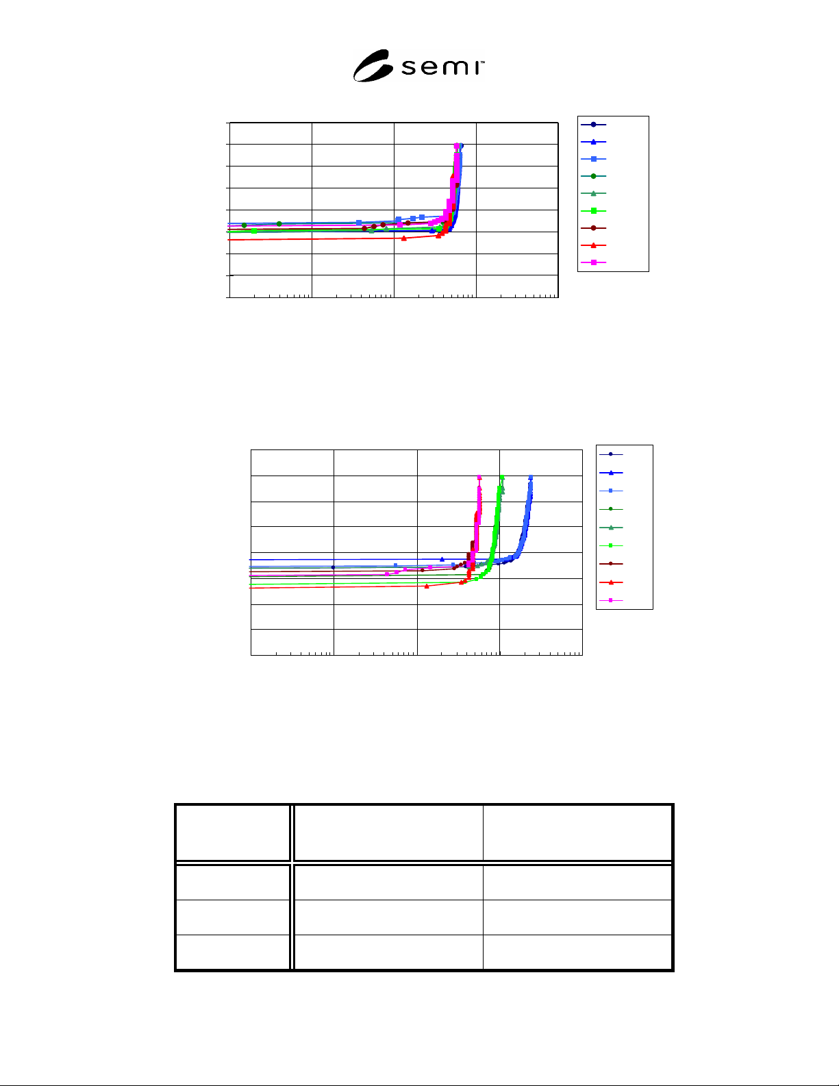
Figure R1-5
Current Density Dependence of Q
BD
. 1mm
2
, 125ºC
-5.00
-4.00
-3.00
-2.00
-1.00
0.00
1.00
2.00
3.00
1.E-02 1.E-01 1.E+00 1.E+01 1.E+02
Qbd (C/cm
2
)
Ln(-Ln(1-F))
R.T
R.T
R.T
85C
85C
85C
125C
125C
125C
Figure R1-6
Temperature Dependence of Q
BD
. J=0.1A/cm
2
, 125ºC
Table R1-2 Current Density Dependence of Q
BD
. (Area = 1mm
2
, Temperature = 125ºC)
SEMI M60-0305 © SEMI 2005 19
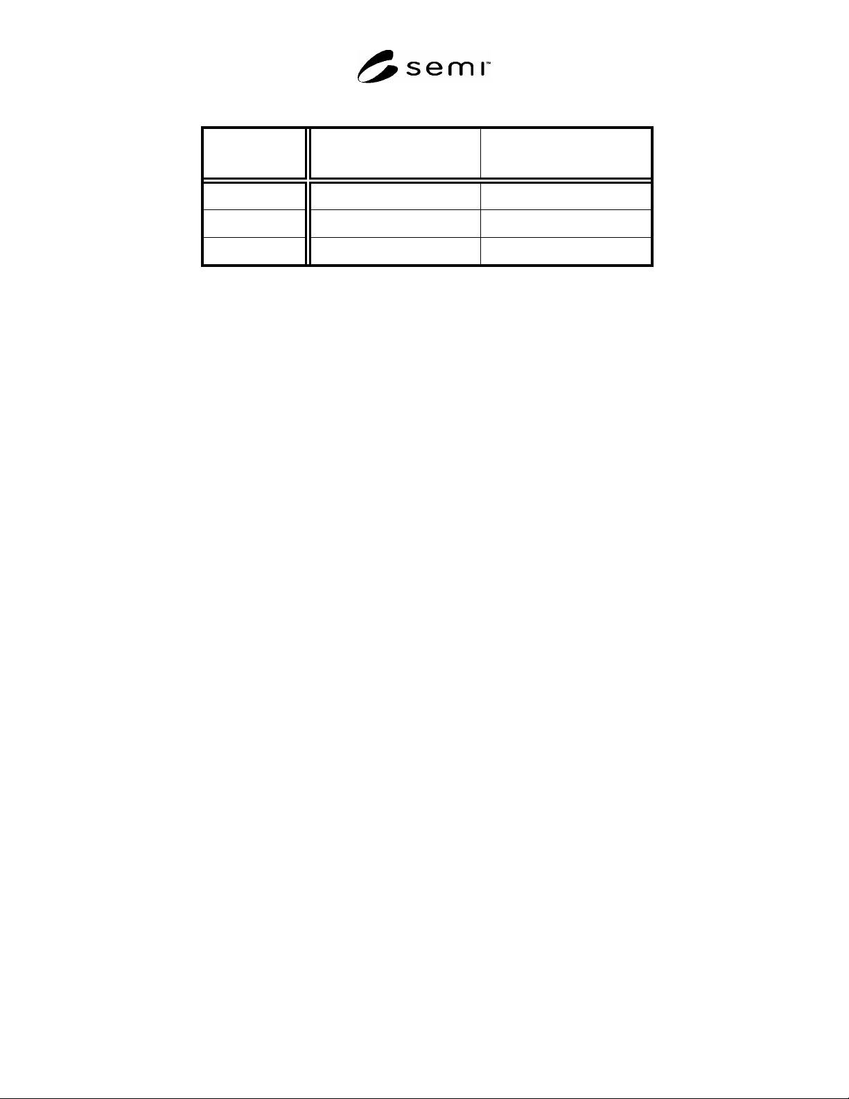
Table R1-3 Temperature Dependence. (Area = 1mm
2
, J = 0.1 A/cm
2
)
NOTICE: SEMI makes no warranties or representations as to the suitability of the standards set forth herein for any
particular application. The determination of the suitability of the standard is solely the responsibility of the user.
Users are cautioned to refer to manufacturer's instructions, product labels, product data sheets, and other relevant
literature, respecting any materials or equipment mentioned herein. These standards are subject to change without
notice.
By publication of this standard, Semiconductor Equipment and Materials International (SEMI) takes no position
respecting the validity of any patent rights or copyrights asserted in connection with any items mentioned in this
standard. Users of this standard are expressly advised that determination of any such patent rights or copyrights, and
the risk of infringement of such rights are entirely their own responsibility.
Temp.
(degree)
Failure (%)
Qbd (C/cm
2
)
at Weibull = 0
r.t. 15.1 19.2
85 14.3 9.2
125 14.8 5.2
Copyright by SEMI® (Semiconductor Equipment and Materials
International), 3081 Zanker Road, San Jose, CA 95134. Reproduction of
the contents in whole or in part is forbidden without express written
consent of SEMI.

SEMI M61-0705 © SEMI 2005 1
SEMI M61-0705
SPECIFICATION FOR SILICON EPITAXIAL WAFERS WITH BURIED
LAYERS
This standard was technically approved by the global Silicon Wafer Committee. This edition was approved
for publication by the global Audits and Reviews Subcommittee on May 20, 2005. It was available at
www.semi.org in June 2005 and on CD-ROM in July 2005.
1 Purpose
1.1 Some silicon epitaxial wafers are supplied with buried layers under the epitaxial film. This specification covers
the properties of such epitaxial wafers that pertain to the buried layer.
2 Scope
2.1 This specification defines the properties of silicon epitaxial wafers with buried layers that relate to the
characteristics of photolithography, buried layer, and buried layer pattern after the deposition of the epitaxial layer.
2.2 This specification is intended to be used with the polished wafer specification (SEMI M1) and the epitaxial
wafer specification (SEMI M2), which define the properties of the substrate and the epitaxial layer, respectively.
2.3 The EDI Code List for items appropriate to epitaxial wafers with buried layers is given in SEMI M18.
NOTICE: This standard does not purport to address safety issues, if any, associated with its use. It is the
responsibility of the user of this standard to establish appropriate safety and health practices and determine the
applicability of regulatory or other limitations prior to use.
3 Referenced Standards and Documents
3.1 SEMI Standards
SEMI M1 — Specifications for Polished Monocrystalline Silicon Wafers
SEMI M2 — Specifications for Silicon Epitaxial Wafers for Discrete Device Applications
SEMI M18 —Format for Silicon Wafer Specification Form for Order Entry
SEMI M20 — Practice for Establishing a Wafer Coordinate System
SEMI M59 — Terminology for Silicon Technology
SEMI MF26 — Test Methods for Determining the Orientation of a Semiconductive Single Crystal
3.2 ANSI Standard
1
ANSI/ASQC Z1.4 — Sampling Procedures and Tables for Inspection by Attributes
3.3 JEITA Standard
2
EM-3501 — Standard methods for determining the orientation of a semiconductor silicon single crystal
NOTICE: As listed or revised, all documents cited shall be the latest publications of adopted standards.
4 Terminology
4.1 General terminology for silicon wafers and silicon technology is covered in SEMI M59 to be published in
March).
4.2 Terms related to epitaxial wafers with buried layers are as follows:
4.2.1 alignment precision — pattern displacement in first mask photolithography process.
1 American National Standards Institute, New York Office: 11 West 42nd Street, New York, NY 10036, USA. Telephone: 212.642.4900; Fax:
212.398.0023 Website:
www.ansi.org
.
2 Japan Electronics and Information Technology Industries Association, 3rd floor, Mitsui Sumitomo Kaijo Bldg. Annex, 11, Kanda-Surugadai 3-
chome, Chiyoda-ku, Tokyo 101-0062, Japan. Tel:81.3.3518.6434; Fax:81.3.3295.8727
Website:www.jeita.or.jp