semi合集-English.pdf - 第4058页
SEMI F54-1000 © SEMI 2000 3 narrow band width. The mobility band width of the extracted aerosol mus t be no greater than 20% of the mean particle m obility. The method for calcu lati ng electrical mobility a nd mobility …

SEMI F54-1000 © SEMI 2000 2
6 Summary of Method
6.1 The measurement is performed using aerosol
standards consisting of NaCl particles suspended in air.
Aerosols are produced by nebulizing a solution of NaCl
in water. After drying and charge neutralization,
particles of the required size are extracted from the
aerosol using an electrostatic classifier (EC). The
concentration of particles in the resulting monodisperse
aerosol is then recorded by the CNC and compared to
that measured simultaneously by a reference
instrument. Examples of suitable reference instruments
are described in Section 8.8.
NOTE 4: This method has been shown to provide repeatable
results in tests performed in separate laboratories on similar
CNCs. Examples of these tests are found in Agarwal and
Sem
3
and Bartz, et al
4
.
7 Requirements
7.1 The reference instrument must have a proven
counting efficiency
of not less than 95% over the entire
range of particle sizes tested. Low counting efficiency
in the reference instrument results in an error in the
measured particle concentration. The counting
efficiency for the reference instrument must be checked
by the manufacturer against a calibrated standard, such
as a calibrated aerosol electrometer.
7.2 Coincidence error in either the CNC or the
reference instrument causes inaccuracy in the measured
particle concentration. The concentration limit for each
instrument must be obtained from the manufacturer’s
specifications. The particle concentration in the aerosol
standard must be kept below both concentration limits.
7.3 When an aerosol electrometer is used as the
reference instrument, the minimum detectable particle
concentration must be obtained from the manufacturer’s
specifications. A particle concentration below the
minimum detectable value will cause inaccurate results.
The particle concentration in the aerosol standard must
be kept above the minimum detectable particle
concentration.
7.4 The transport loss of particles from the EC to the
CNC, and from the EC to the reference instrument must
be checked. Any disparity in particle transport loss to
the two instruments will cause erroneous results. The
method for calculating the transport loss of particles in
3 Agarwal, J. K. and Sem, G. J. Continuous Flow, Single-Particle-
Counting Condensation Nucleus Counter. Journal of Aerosol
Science, 11: 343-357 (1980)
4 Bartz, H., Fissan, H., Helsper, C., Kousaka, Y., Okuyama, K.,
Fukushima, N., Keady, P. B., Kerrigan, S., Fruin, S. A., McMurry, P.
H., Pui, D. Y. H. and Stolzenburg, M. R. Response Characteristics for
Four Different Condensation Nucleus Counters to Particles in the 3-
50 nm Diameter Range. Journal of Aerosol Science, 16 (5): 443-456
(1985)
sample lines is found in Pui, et al
5
. The transport loss
must be calculated for each particle size tested. Record
all transport loss calculations.
7.5 When an aerosol electrometer is used as the
reference instrument, a correction must be made for
multiple charging of particles in the aerosol standard.
Multiple charging can cause substantial error when
measuring particles larger than 0.06 micrometer. The
correction factor for multiple charging must be obtained
from the manufacturer of the EC. An example of the
method for calculating the correction factor is found in
Liu and Pui
6
.
8 Apparatus
8.1 Atomizer — A sub-micrometer aerosol generator
capable of nebulizing a liquid solution. The atomizer
must be capable of producing a stable aerosol
containing particles as small as 0.01 micrometer after
drying.
8.2 Liquid Trap — A device which allows free
passage of an aerosol stream containing sub-micrometer
particles, but which removes the entrained liquid phase
by gravitational settling into a reservoir.
8.3 Diffusion Drier — A device which allows free
passage of an aerosol stream containing sub-micrometer
particles, but which dries the aerosol by diffusion of
water vapor into a surrounding desiccant medium. The
design flow rate of the diffusion drier must at least
match the output flow rate of the atomizer.
8.4 Aerosol Neutralizer — A bipolar charging device
which neutralizes aerosols by producing both positive
and negative air ions. The neutralizer must reduce the
charge on the particles to the Boltzmann equilibrium
level. The design flow rate of the neutralizer must at
least match the output flow rate of the atomizer.
8.5 Bypass Filter — A high efficie ncy point of use gas
filter. The design flow rate of the bypass filter must at
least match the output flow rate of the atomizer.
8.6 Mixing Vessel — A device which disperses
particles in a flowing aerosol by inducing turbulence.
8.7 Electrostatic Classifier (EC) — A device which
extracts particles from a polydisperse aerosol according
to their electrical mobility. The electrical mobility of a
particle depends upon its size and charge. The
EC must
extract a monodisperse aerosol standard having a
5 Pui, D. Y. H, Ye, Y. and Liu, B. Y. H. Sampling, Transport, and
Deposition of Particles in High Purity Gas Supply System.
Proceedings 9th ICCCS: 287-293, (1988)
6 Liu, B. Y. H. and Pui, D. Y. H. A Submicron Aerosol Standard and
the Primary, Absolute Calibration of the Condensation Nuclei
Counter. Journal of Colloid and Interface Science, 47 (1): 155-171
(1974)
SEMI F54-1000 © SEMI 20003
narrow band width. The mobility band width of the
extracted aerosol must be no greater than 20% of the
mean particle mobility. The method for calculating
electrical mobility and mobility band width are found in
Liu and Pui
6
.
8.8 Reference Instrument — An instrument which can
measure the concentration of particles in an aerosol.
The calibration of the reference instrument must have
been checked against a calibrated standard within the
past 12 months. Calibration and maintenance records
for the reference instrument must be maintained.
Suitable reference instruments include aerosol
electrometers and CNCs having lower size sensitivities
below 0.01 micrometer.
8.9 Condensation Nucleus Counter (CNC) or
Condensation Particle Counter (CPC) — The particle
counter to be used in process gas particle
measurements, and for which the calibration check is
required. The CNC detects sub-micrometer particles
using nucleation and droplet growth of a super-
saturated working fluid.
8.10 Tubing — In order to minimize particle losses, all
tubing used to transport charged aerosol particles must
be constructed from electrically conductive materials
(e.g., stainless steel) and grounded.
9 Reagents and Materials
9.1 De-ionized or distilled water in accordance with
ASTM D1193, Type 1 is required to dissolve NaCl for
aerosol generation.
9.2 NaCl is required for aerosol generation.
9.3 A supply of dry, oil-free compressed air is
required to generate and transport aerosols in the
apparatus.
10 Preparation of Apparatus
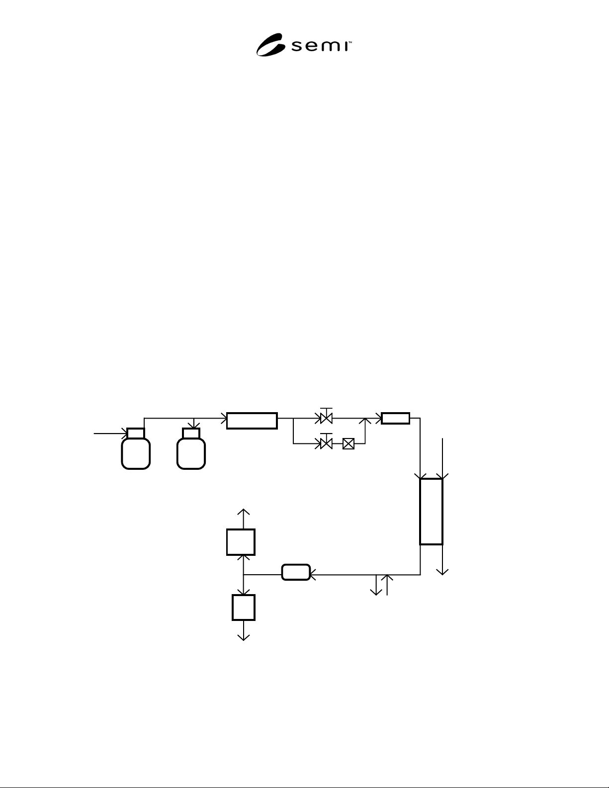
10.1 The test apparatus is shown in Figure 1. The
particle concentration in the aerosol is controlled using
a bypass filter. If the flow rate of the monodisperse
aerosol from the EC is insufficient to supply the CNC
and reference instrument simultaneously, filtered air
must be added to the stream. The air must be added to
the aerosol upstream of a mixing vessel. If the flow
rate of the monodisperse aerosol from the EC is greater
than that required to supply the CNC and reference
instrument simultaneously, the excess aerosol must be
vented.
Compressed
Air
Liquid
Trap
Diffusion
Drier
Bypass Filter
for Dilution
A
erosol
Neutralizer
A
tomizer
Sheath Air
Excess Air Vent
Electrostatic
Classifier
Monodisperse
Reference
Instrument
Nucleus
Counter
Filtered
Filtered
Mixing
Vessel
Filtered Make-Up Air
or Excess Aerosol Vent
A
erosol Standard
Condensation
Vent
V
ent
(CNC)
(EC)
Figure 1
Schematic Diagram of Test Apparatus
SEMI F54-1000 © SEMI 2000 4
11 Calibration and Standardization
11.1 All flow meters and voltage indicators used in the
apparatus, including instruments incorporated into the
EC and particle counters, must have been checked for
proper calibration against calibrated standards within
the past 12 months. Record all calibration data.
12 Procedure
12.1 Fill the atomizer reservoir with a solution of NaCl
in water. The required NaCl concentration depends
upon the range of particle sizes to be tested, and must
be determined from the atomizer manufacturer’s
specifications. Record the concentration of NaCl in the
solution.
12.2 Determine the required aerosol, sheath air and
excess air flow rates for the EC. The flow rates depend
upon the range of particle sizes to be tested and the
required mobility bandwidth, and must be determined
from the EC manufacturer’s specifications.
12.3 Close the bypass filter valve. Adjust the flow
rates of the atomizer, CNC, and reference instrument to
their manufacturer’s specified values. Adjust the flow
rates of the
EC to their required values as described in
Section 12.2. Adjust the flow rate of the make-up air or
aerosol vent to the required value as described in
Section 10.
12.4 Set the EC voltage to obtain the selected particle
size for testing. Record the voltage setting and the
selected particle size.
12.5 Observe the particle concentration indicated by
the reference instrument. If the particle concentration
exceeds the concentration limit of the reference
instrument or the CNC, adjust the flow rate through the
bypass filter to lower the aerosol particle concentration.
After adjusting the bypass flow rate, check all flow
rates to ensure that they remain at the required values.
Record all flow rates.
12.6 Wait for the particle concentrations indicated by
the CNC and reference instrument to become steady;
the concentrations indicated by each instrument must
not change by more than 5% over a five minute
interval. In order to minimize the error in the recorded
particle concentrations, a minimum of 500 particles
must be counted in a sample. Record the steady
particle concentrations indicated by the CNC and
reference instrument.
12.7 If another particle size is to be tested, return to
Section 12.4.
NOTE 5: At least eight different particle sizes must be tested.
The particle sizes must be selected such that the measured
CNC counting efficiency at least spans the range 50% to 95%
(0.50 to 0.95). In order to eliminate systematic error, the
particles sizes must be tested in random order.
13 Calculation and Interpretation of Results
13.1 When an aerosol electrometer is used as the
reference instrument, correct the measured particle
concentrations for multiple charging, as described in
Section 7.5.
13.2 For each particle size tested, calculate the ratio of
the concentration of particles reported by the CNC to
that reported by the reference instrument. This ratio
represents the counting efficiency of the CNC.
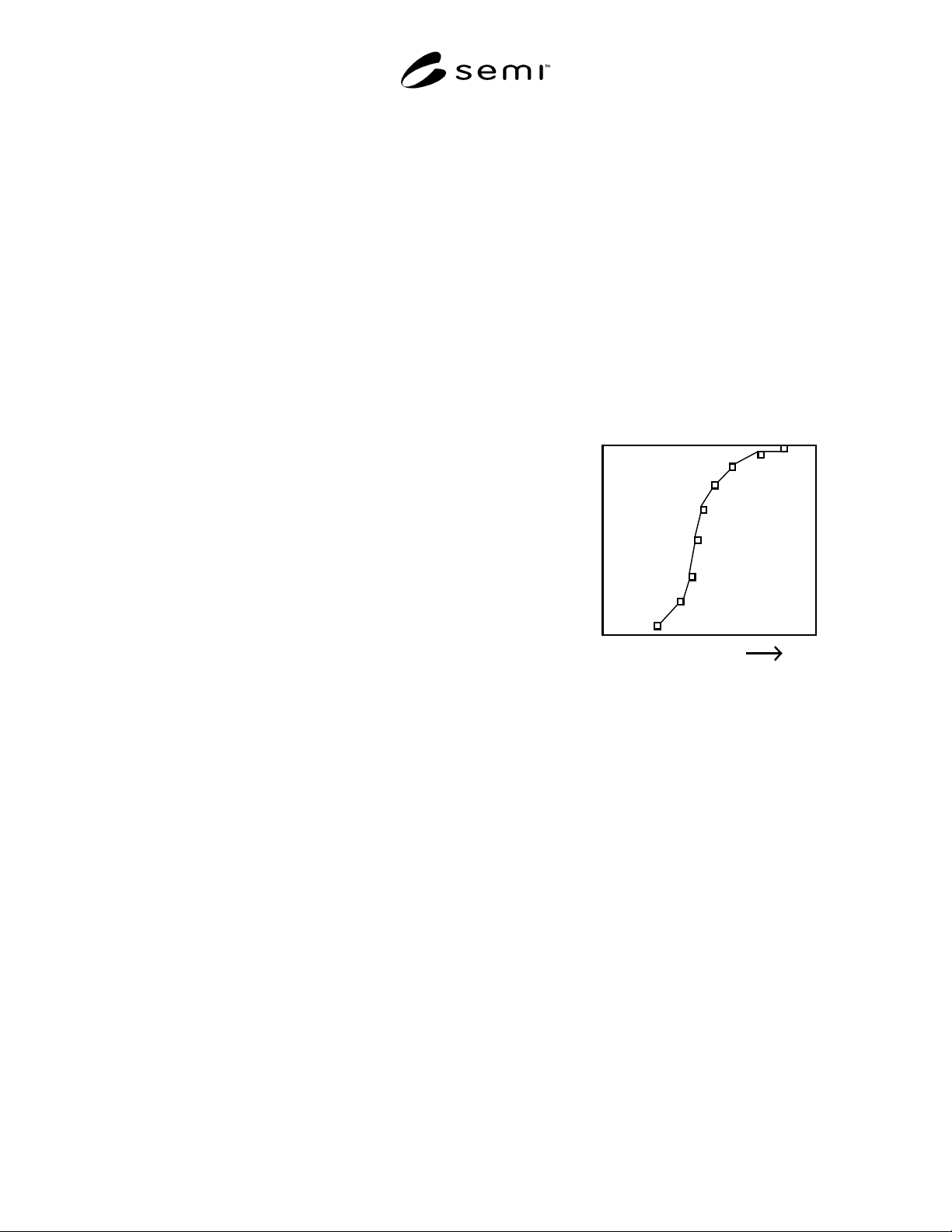
13.3 Plot the calculated counting efficiency against the
particle size as shown in Figure 2. This plot shows the
measured counting efficiency curve of the CNC.
Particle Size
Counting Efficienc
y
0
1
Figure 2
Schematic Plot of Measured Counting Efficiency
13.4 Determine the lower size sensitivity of the CNC,
as defined in Section 5. (The counting efficiency at any
particle size can be estimated using linear interpolation
between the data points.)
14 Reporting Results
14.1 The test record must include the following items:
a. test date;
b. test operator;
c. serial numbers of the reference instrument, CNC
and EC;
d. all particle transport loss calculations as described
in Section 7.4;
e. all flow meter and voltage indicator calibration
data as described in Section 11;
f. all raw data and calculations utilized in the test
method as listed in Sections 12 and 13;