semi合集-English.pdf - 第329页
SEMI E49.4-0298 © SEMI 1995, 1998 3 Table 1 Summary of Recommended Specific ations Description Value Units Internal Surface Che mistry (AUGER) Surface chromiu m oxide enh anced layer thickness at 1/2 peak height of measu…

SEMI E49.4-0298 © SEMI 1995, 1998 2
6.5 Incoming process liquids require filters and should
be located downstream of any regulator and as close as
possible to point of dispense.
6.6 Design should include a means of flow through
flushing and draining for removable components or
assemblies.
6.7 Pumping systems should include surge/pulse
suppression devices and provisions for vibration
isolation.
6.8 Supply and drain lines on a recirculation system
should be separated by an isolation valve. The system
should not use one line to perform both functions.
6.9 All filters should be able to be isolated from
process stream for maintenance.
6.10 Backflow/back pressure protection should be
included in the system.
6.11 For processes requiring pressu re control,
regulators should be included in the system.
6.12 The system should have a means of manifolding
supply and drain lines onboard, so that there is a single
point connection for each individual liquid.
7 Materials Guidelines
7.1 Material Mechanical Characte ristics - Stainless
Steel
7.1.1 All tubing greater than or equal to 1.27 cm (1/2
in.) diameter should conform to ASTM A 269.
7.1.2 Tubing less than 1.27 cm (1/2 in.) diameter
should conform to ASTM A 632.
7.1.3 All bar stock should conform t o ASTM A 479 or
ASME SA479.
7.1.4 All steel should conform to ASM UNS S31603
for chemical composition with the following
exceptions:
• Sulfur as reported by the SMTR ≤ 0.030%
• Carbon as reported by the SMTR ≤ 0.030%
7.2 Stainless steel should be 316L electropolished for
solvent system wetted flow streams or as specified by
the customer.
7.3 Materials for valve seats, diaphragms, gaskets, and
O-rings should be chemically compatible to the process
liquid.
7.4 Material Performance Guidelines
7.4.1 The performance guidelines below are SS
qualification values to be demonstrated by the original
component manufacturer. Semiconductor equipment
suppliers should provide proof that their components
conform to these requirements.
7.4.2 The performance tests should be considered
production qualification tests. It is the responsibility of
the component manufacturer to provide statistically
significant data which correlates their production tests
to these qualification tests (e.g., Statistical Process
Control, MIL-STD-105D).
7.4.3 The equipment supplier should be responsible
for maintaining and supplying, upon request,
documentation that proves their components meet the
user’s materials performance requirements.
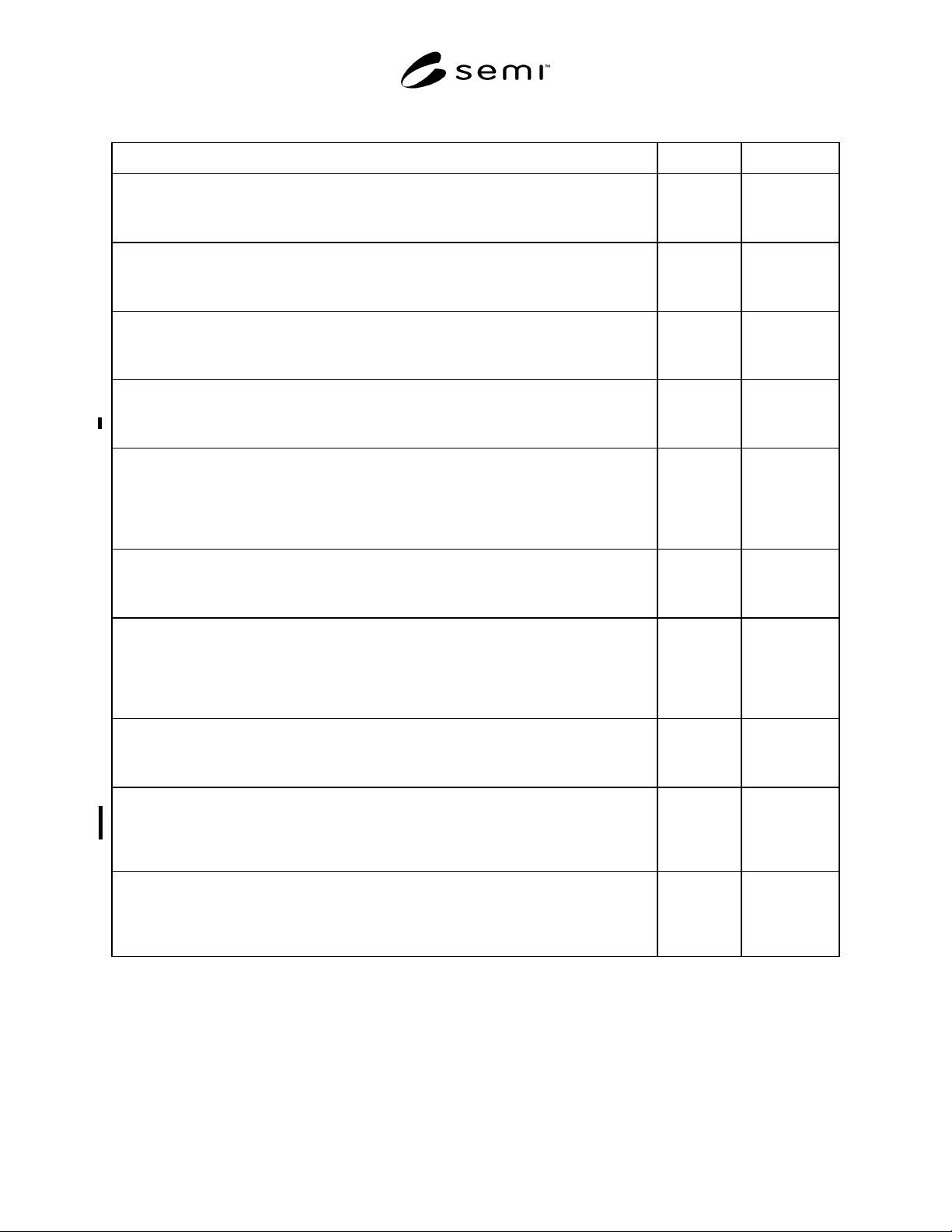
SEMI E49.4-0298 © SEMI 1995, 19983
Table 1 Summary of Recommended Specifications
Description Value Units
Internal Surface Chemistry (AUGER)
Surface chromium oxide enhanced layer thickness at
1/2 peak height of measured oxygen signal level
For an example of a test method, see SEMASPEC 90120573B (ESCA)
≥ 15 Å
Internal Surface Chemistry (ESCA)
Total chromium to iron ratio including both reduced
and oxidized stated
For an example of a test method, see SEMASPEC 90120403B (ESCA)
≥ 1.25:1 value
Internal Surface Chemistry (EDX)
Surface foreign elements, those elements not in the
Smelter’s Test Report (SMTR)
Test procedures per ASTM F 1375 (EDX)
0value
Internal Surface Defects
Photos per test method
Counts per photo
Test procedures per ASTM F 1375 (SEM)
5
≤ 50
value
value
Internal Surface Roughness
Average surface roughness
Roughness average (R
a
)
Maximum surface R
a
(individual reading)
For example of a test method, see SEMASPEC 90120400B (Contact Profilometry)
≤ 0.25
(≤ 10)
≤ 0.38
(≤ 15)
µm
(µin.)
µm
(µin.)
Particulate Contribution
at ≥ 0.1 µm size
at ≥ 0.02 µm size
Test procedures per ASTM F 1394 (Particles)
≤ 0.71 (20)
≤ 2.6 (75)
ptc/L (ptc/ft
3
)
ptc/L (ptc/ft
3
)
Internal Absorbed Moisture
Time to recover to base line from a 2 ppm spike
for low surface area component (valve, regulator)
Time to recover to baseline from a 2 ppm spike
for high surface area component (filters, tubing)
Test procedures per ASTM F 1397
≤ 4
≤ 6
hour
hour
Total Anionic Contamination
Total anionic contamination added to test water
Individual anionic contaminant
Test procedures per ASTM D 4327 (Total Anions)
≤ 1
≤ 0.2
ppm
ppm
Leak Rate
Inboard leak rates for He
Outboard leak rate for He
Cross-seat leak rates for He
Test procedures per SEMI F1 (Leak Rate)
≤ 1 × 10
-9
≤ 1 × 10
-5
≤ 1 × 10
-8
scc/s
scc/s
scc/s
Cycle Life
Manual values pressure automatic valves
High Pressure automatic valves
Low Pressure automatic valves
Test procedures per ASTM F 1375 (Cycle Life)
≥ 25 K
≥ 25 K
≥ 500 K
cycles
cycles
cycles

SEMI E49.4-0298 © SEMI 1995, 1998 4
8 Component Guidelines
8.1 For component leak rate and c ycle life
requirements, see Section 7, Materials Guidelines.
8.2 Valves should be ball (dry asse mbly, lubricant-
free) or bellows type. Metal diaphragm valves are
optional.
8.3 Regulators should be packless in design with all
metal bonnet seals.
8.4 Regulators and valve flow coefficient (C
v
) should
be selected based on liquid flow requirements and
liquid characteristics.
8.5 Mechanical fittings should be compression type or
metal face seal type with solid nickel gaskets.
8.6 Pressure gauges should be liquid-filled type with
compression or metal face seal fittings. Gauge isolators
are recommended.
8.7 Filters should be PTFE media rated at 0.1 µm pore
size.
8.8 Check valves should be disk poppet type.
9 Subsystem Assembly Gui delines
See SEMI E49.6 for recommended SS system assembly
procedures.
10 Related Documents
10.1 SEMATECH Documents
4
SEMASPEC 90120400B — Test Method for
Determination of Surface Roughness by Contact
Profilometry for Gas Distribution System Components
SEMASPEC 90120403B — Test Method for XPS
Analysis of Surface Composition and Chemistry of
Electropolished Stainless Steel Tubing for Gas
Distribution System Components
SEMASPEC 90120573B — Test Method for AES
Analysis of Surface and Oxide Composition of
Electropolished Stainless Steel Tubing for Gas
Distribution System Components
4 SEMATECH, Technology Transfer Department, 2706 Montopolis
Drive, Austin, TX 78741
NOTICE: These standards do not purport to address
safety issues, if any, associated with their use. It is the
responsibility of the user of these standards to establish
appropriate safety and health practices and determine
the applicability of regulatory limitations prior to use.
SEMI makes no warranties or representations as to the
suitability of the standards set forth herein for any
particular application. The determination of the
suitability of the standard is solely the responsibility of
the user. Users are cautioned to refer to manufacturer’s
instructions, product labels, product data sheets, and
other relevant literature respecting any materials
mentioned herein. These standards are subject to
change without notice.
The user’s attention is called to the possibility that
compliance with this standard may require use of
copyrighted material or of an invention covered by
patent rights. By publication of this standard, SEMI
takes no position respecting the validity of any patent
rights or copyrights asserted in connection with any
item mentioned in this standard. Users of this standard
are expressly advised that determination of any such
patent rights or copyrights, and the risk of infringement
of such rights, are entirely their own responsibility.
Copyright by SEMI® (Semiconductor Equipment and Materials
International), 3081 Zanker Road, San Jose, CA 95134. Reproduction o
f
the contents in whole or in part is forbidden without express written
consent of SEMI.