semi合集-English.pdf - 第900页
SEMI E117-1104 © SEMI 2002, 2004 2 6 Requirements 6.1 Figures and Tables — The dim ensional requirements for a reticle load port (and for the placement of an RSP on that load port ) are given in Table 1 with reference to…
SEMI E117-1104 © SEMI 2002, 2004 1
SEMI E117-1104
SPECIFICATION FOR RETICLE LOAD PORT
This specification was technically approved by the Global Physical Interfaces and Carriers Committee and is
the direct responsibility of the North American Physical Interfaces and Carriers Committee. Current edition
approved by the North American Regional Standards Committee on August 16, 2004. Initially available at
www.semi.org September 2004; to be published November 2004. Originally published November 2002;
previously published March 2003.
1 Purpose
1.1 This specification defines dimensional
requirements and options of reticle load ports on reticle
stockers, lithography exposure equipment, and reticle
inspection equipment. It is intended to promote a
uniform physical interface between equipment and the
factory, to facilitate the use of automated RSP transport
systems, and/or to meet ergonomic requirements for
manually loaded equipment.
2 Scope
2.1 This standard covers only load ports for reticle
SMIF pods (RSPs) as specified in SEMI E100, E111,
and E112. Similar requirements and options covering
load ports for wafers are covered in SEMI E15 (for 200
mm wafers and smaller) and in SEMI E15.1 (for 300
mm wafers).
NOTICE: This standard does not purport to address
safety issues, if any, associated with its use. It is the
responsibility of the users of this standard to establish
appropriate safety health practices and determine the
applicability or regulatory limitations prior to use.
3 Referenced Standards
3.1 SEMI Standards
SEMI E15 — Specification for Tool Load Port
SEMI E15.1 — Specification for 300 mm Tool Load
Port
SEMI E19.3 — Port Standard for Mechanical Interface
of Wafer Cassette Transfer, 150 mm (6 inch) Port
SEMI E19.4 — 200 mm Standard Mechanical Interface
(SMIF)
SEMI E72 — Specification and Guide for 300 mm
Equipment Footprint, Height, and Weight
SEMI E100 — Specification for a Reticle SMIF Pod
(RSP) Used to Transport and Store 6 inch or 230 mm
Reticles
SEMI E111 — Provisional Mechanical Specification
for a 150mm Reticle SMIF Pod (RSP150) Used to
Transport and Store a 6 Inch Reticle
SEMI E112 — Provisional Mechanical Specification
for a Multiple 150 mm Reticle SMIF Pod (MRSP150)
Used to Transport and Store 6 Inch Reticles
NOTICE: As listed or revised, all documents cited
shall be the latest publications of adopted standards.
4 Terminology
4.1 Definitions
4.1.1 150 mm Multiple Reticle SMIF Pod (MRSP150)
— a minienvironment compatible carrier (as defined in
SEMI E112) that is capable of holding six 6 inch
reticles in a horizontal orientation during transport and
storage and is compatible with a Standard Mechanical
Interface (SMIF) per SEMI E19.3.
4.1.2 150 mm Reticle SMIF Pod (RSP150) — a
minienvironment compatible carrier (as defined in
SEMI E111) that is capable of holding one 6 inch
reticle in a horizontal orientation during transport and
storage and is compatible with a Standard Mechanical
Interface (SMIF) per SEMI E19.3.
4.1.3 200 mm Reticle SMIF Pod (RSP200) — a
minienvironment compatible carrier (as defined in
SEMI E100) that is capable of holding one 6 inch
reticle or one 230 mm reticle in a horizontal orientation
during transport and storage and is compatible with a
Standard Mechanical Interface (SMIF) per SEMI
E19.4.
4.1.4 Reticle SMIF Pod (RSP) — a minienvironment
compatible carrier that is capable of holding either one
or six reticles in a horizontal orientation during
transport and storage and is compatible with a Standard
Mechanical Interface (SMIF) per SEMI E19.3 or SEMI
E19.4.
NOTE 1: All other terminology from SEMI E100, E111,
E112, and E15 also apply (except that in SEMI E15, the
substrate must be assumed to be a reticle and not a wafer).
5 Ordering Information
5.1 The user must specify which RSPs will be used:
RSP200, RSP150, MRSP150, or both RSP150 and
MRSP150.

SEMI E117-1104 © SEMI 2002, 2004 2
6 Requirements
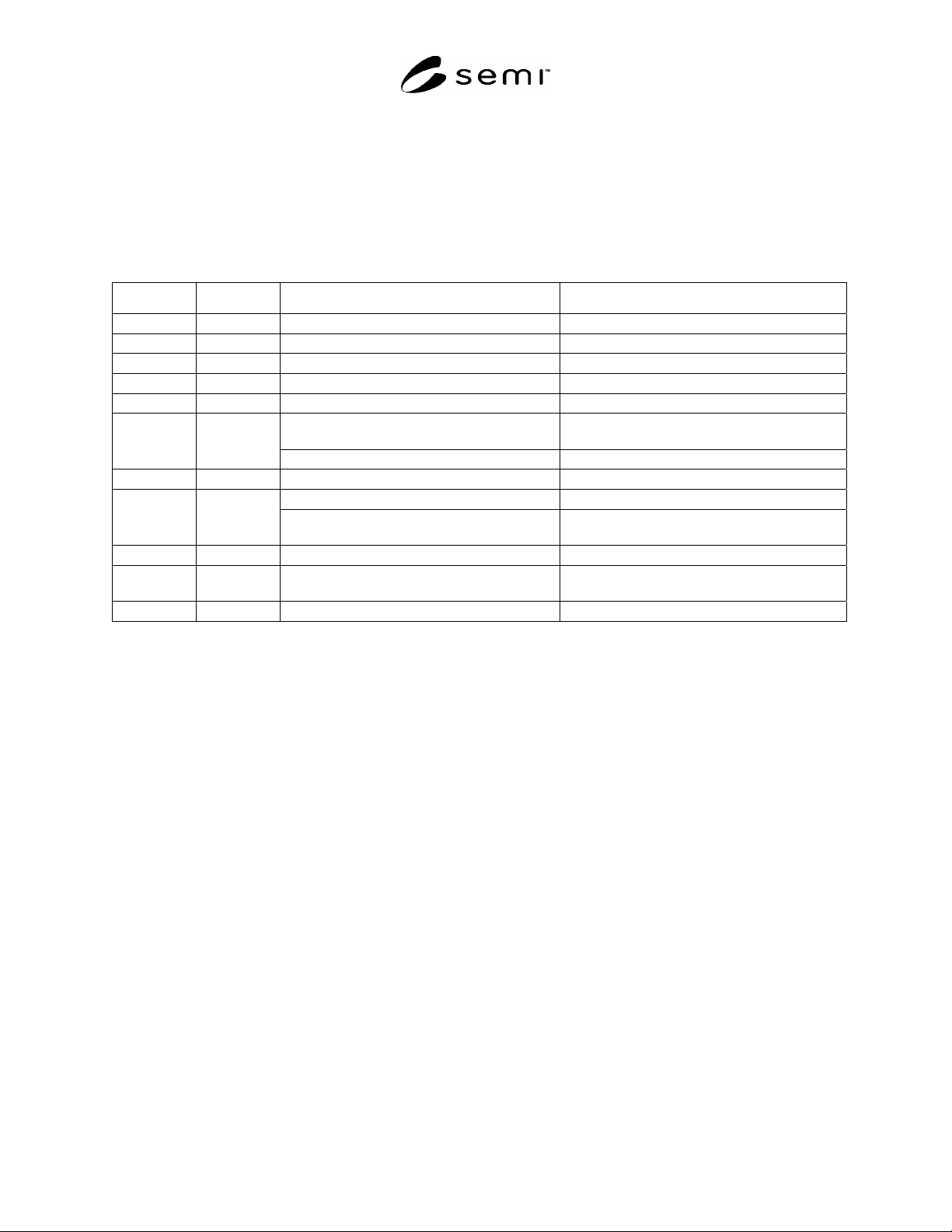
6.1 Figures and Tables — The dimensional
requirements for a reticle load port (and for the
placement of an RSP on that load port) are given in
Table 1 with reference to the figures in this document.
Although the carrier transport systems shown in these
figures represent an overhead transport system using an
OHT delivery vehicle, they are intended to represent all
types of transport systems (AGV, PGV, conveyor,
overhead track, etc.).
6.2 Orientation — The reticles are to be oriented
horizontally (chrome down) with zero nominal tilt
when the RSP is placed on the load port. The tolerance
in the horizontal plane is determined by the registration
and alignment feature between the RSP and the load
port, as specified in SEMI E19.3 or SEMI E19.4. The
RSP shall be loaded and unloaded with its front (where
reticles are inserted and extracted after the SMIF pod is
opened) parallel to and away from the load face plane
(see Figure 2).
6.3 Side Clearances — Clearances C1 and C2 are
defined with respect to the maximum dimensions of the
footprint of the RSP (as specified in SEMI E19.3 or
SEMI E19.4), not to the rectangular carrier envelope
(defined in SEMI E15). Note that C1 is lateral clearance
to the left and right of the RSP, but C2 is a radial
clearance from the nearest point of the RSP.
6.4 Overhead Clearances — All load ports intended
for automated overhead access must be open from
above to facilitate automatic RSP delivery. The open
volume required for automated overhead delivery is
defined by a projection of the load port area, including
the area required for C1 and C2 clearances, projected
upward to the top of the equipment. To allow space for
overhead delivery above H2, D1 also defines the open
volume. Note that this condition need only be met when
the equipment is being loaded or unloaded. For
example, the load port may be formed by a surface that
extends outward during loading to provide overhead
access.
6.5 Easement for Overhead Transport — As shown in
Figure 1 and Figure 2, to add clearance for overhead
RSP transport, no part of the equipment may be higher
than H2 above the floor along an easement between the
load ports of adjacent equipment down the bay. On a
reticle stocker, on inspection equipment, and on
lithography exposure equipment that has the load ports
on the far end from the litho track, this easement is
between the load face plane and a plane parallel to it
that is D1 beyond the facial reference plane. On
lithography exposure equipment that has the load ports
on a side adjacent to the litho track, this easement is
between two planes parallel to the bilateral reference
plane at the furthest reach of clearance C1 to the left
and right of the set of load ports. Such tools must also
have an additional easement above H6 between the load
face plane and a plane parallel to it that is D1 beyond
the facial reference plane. It is recommended that
transport equipment using these easements have extra
clearance to avoid contacting any equipment
boundaries.
6.6 Loading Obstructions — As shown in Figure 3, the
maximum allowable height of an obstruction on the
load port over which the RSP must be lifted (before
being set down on the SMIF interface) is H1.
Examples of such obstructions include alignment
devices and identification tag readers (as well as the
SMIF port itself). In the volume between the horizontal
reference plane and H1 above it, clearances C1 and C2
no longer apply.
6.7 Load Port Lead In — The load port must provide a
lead-in capability (in addition to that required on the
SMIF port) that corrects an RSP misalignment distance
of R in any horizontal direction.
6.8 Adjacent Load Ports — All reticle load ports for
automated access must be on the same side of the
equipment. All equipment must have at least one load
port with access for automated overhead delivery. At
least two of these load ports are recommended to
support equipment throughput. Auxiliary load ports
intended for manual delivery may be located on a
different side of the equipment. On each piece of
equipment, reticle load ports are numbered in
increasing order (beginning with 1) from left to right
(as seen by a person facing the load face plane)
beginning with reticle load ports in the lowest level and
then continuing (from left to right) with any reticle load
ports at higher levels. Dimension S specifies the
spacing between adjacent reticle load ports.
6.9 As shown in Figure 4, reticle load ports must
conform to one of the following configuration options.
If no option is specified, Option 1 is assumed.
6.9.1 In Option 1, the load port must nominally be at
H, and it must be open from above to facilitate
automatic carrier delivery from an overhead transport
system. The open volume required for vertical delivery
is defined by a projection of the tool load port area,
including the area required for C1 and C2 clearances,
projected upward to the top of the tool. Note that this
condition need only be met when the tool is being
loaded. For example, the load port may be formed by a
surface that extends outward during loading to provide
overhead access.
6.9.2 In Option 2 (which allows faster automatic
carrier delivery from an overhead transport system), the
top of the carrier must be H2 (2900 for exposure
SEMI E117-1104 © SEMI 2002, 2004 3
equipment), and it must be open from above to facilitate
automatic carrier delivery from an overhead transport
system.
6.9.3 In Option 3 (with no allowance for automatic
carrier deliver from an overhead transport system), the
top of the carrier must be H2 (2900 for exposure
equipment), clearance above the reticle must be C3.
6.9.4 Additional load ports used for manual
loading/unloading can be located below the primary
load port in each of the three options.
6.9.5 Equipment suppliers and users should note that
SEMI S8 requirements might restrict such
implementations of manual load ports.
Table 1 Dimensional Requirements for Reticle Load Ports
Dimension Application Value, mm (in.) Notes
C1 minimum 75 (3.0) Clearance to left and right of RSP.
C2 minimum 50 (2.0) Radial clearance around RSP.
C3 minimum 150 (5.91)
D maximum 250 (9.8) Load face plane to facial reference plane.
D1 minimum 196 (7.72) Facial reference plane to OHT easement.
H range
minimum 890 (35.0)
maximum 2690 (106)
Port height: lithography exposure equipment.
925 ± 35 (36.4 ± 1.4) Reticle stockers and inspection equipment.
H1 maximum 60 (2.36) Loading obstruction height at load port.
2900 (114.2) OHT easement height: exposure equipment.
H2 maximum
2600 (102.4)
Reticle stockers and inspection equipment
(recommended for exposure equipment).
H6 maximum 3200 (126) Side OHT easement height (see Figure 2b).
R
minimum
10 (0.4) required
15 (0.6) recommended for ergonomic reasons
Load port lead-in capability (correction of RSP
misalignment in any horizontal direction).
S minimum 290 (11.4) [358 (14.1)] Spacing of adjacent load ports.
#1
In Table 1 and in the figures of this document, numbers in [square brackets] are specific to the RSP200 (if different from the RSP150 and
MRSP150).