semi合集-English.pdf - 第3508页
SEMI E134-0305 © SEMI 2004, 2005 61 RELATED INFORMATION 1 DATA COLLECTION CONTEXT NOTICE : This rel ated infor mation is not an official part of SEMI Exxx and was derived from the wo rk of the originating committee. Th i…

SEMI E134-0305 © SEMI 2004, 2005 60
16 Requirements for Compliance
16.1 Table 88 provides a checklist for Data Collection Management compliance. Note that the DCP State Models
described in Section 12 are internal to the equipment and have no SEMI-specified technology mapping.
Table 88 Data Collection Management Compliance Statement
Fundamental
Requirements
Section Implemented using SEMI
technology mapping
Implementation complies
with specification
Implementation complies with
technology mapping
DCM Interface 9
Yes No Yes No Yes No
DCP Privileges 10
Yes No Yes No Yes No
DCP Definition 11
Yes No Yes No Yes No
DCP State Models 12 N/A
Yes No
N/A
Operational Performance
Monitoring
13
Yes No Yes No Yes No
Data Representation 14
Yes No Yes No Yes No
DCP Notifications 15
Yes No Yes No Yes No
SEMI E134-0305 © SEMI 2004, 2005 61
RELATED INFORMATION 1
DATA COLLECTION CONTEXT
NOTICE: This related information is not an official part of SEMI Exxx and was derived from the work of the
originating committee. This related information was approved for publication by full letter ballot procedures.
R1-1 Overview
R1-1.1 This Related Information discusses some of the key requirements and expectations of the equipment for
applications that make use of Data Collection Management services for performing near-real-time analysis of time
series (trace) data from equipment. The essential goal is for the equipment to provide sufficient, correct, and timely
contextual data to such applications in order to facilitate correct and timely analysis of trace data.
R1-1.2 Typical Analysis Application Example
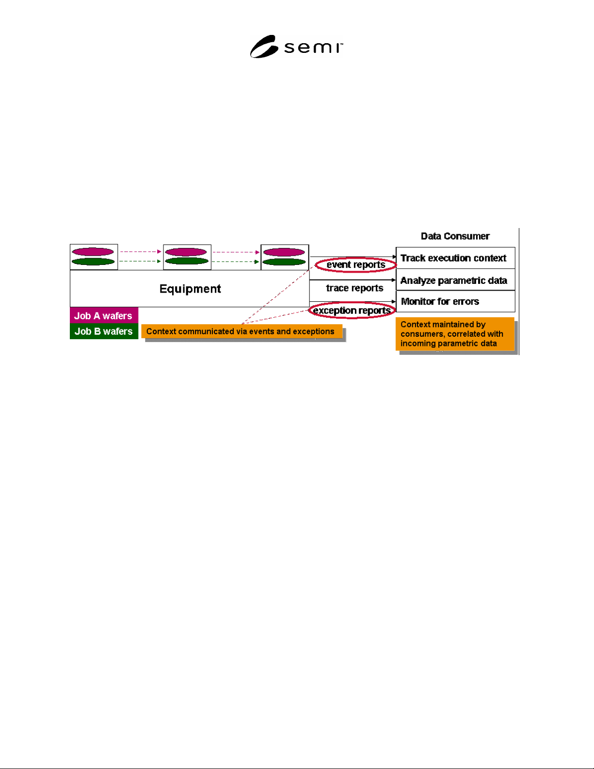
Figure R1-1
Typical Time-Series Data Analysis Example
R1-1.2.2 Consumers that collect trace data from the equipment need to be able to quickly make sense of incoming
data in order to determine the proper analysis and/or limits to apply. In addition to the raw low level data values
from sensors, actuators, and other devices of interest, applications need to be able to quickly determine the executing
context associated with that data. The equipment needs to be able to provide sufficient context information to the
application to allow it to determine at all times:
What module is the data coming from?
What recipe is that module running?
What step is that recipe executing?
What material is in that module?
What job is responsible for that material?
R1-1.2.3 In addition to the information in Section R1-1.2.2 , typical consumers must also know the manufacturing
execution context (for example, whether this an engineering lot, an experimental run, a characterization, a rework
lot, a production run, a specific product, etc.) in order to properly analyze data from the equipment. While it is the
consumer’s responsibility to manage this manufacturing context data, it is the equipment’s responsibility to provide
the context information described in Section R1-1.2.2 .
R1-1.2.4 In many cases, this context data may consist of a non-trivial amount of descriptive information. It is
typically not practical for all of this contextual data to be provided with each TraceReport sent by the equipment.
Trace data may also be collected at rates up to, for example, 10Hz; much more frequently than the rate at which the
job-related context information changes. Because of this situation, it is normally sufficient for the equipment to
communicate context changes when they happen by defining events that are generated whenever any of the context
described in Section R1-1.2.2 changes (see Figure R1-1).
SEMI E134-0305 © SEMI 2004, 2005 62
R1-1.2.5 Along with such events, the equipment must also make available sufficient data with those events to
completely describe the new context, as well as providing a way for consumers to query the current context at any
time in an ad-hoc fashion. Additionally, some subset of this context data can be made available for inclusion with
each TraceReport, such as the id’s of the material at each location in the equipment.
R1-1.2.6 Some of this context data can be provided directly through the SEMI Data Collection Management and
related specifications. Specifically, the Data Collection Management specification requires that all parameters,
events, and exceptions have both a source and a name. The source can be used to specify the physical equipment
component that produces the parameter, event, or exception. This information can be made known to consumers,
for example, through the use of SEMI E120 (Common Equipment Model) and E125 (Equipment Self Description).
In this way, consumers are at all times aware of the physical equipment component from which the data, event, or
exception is coming.
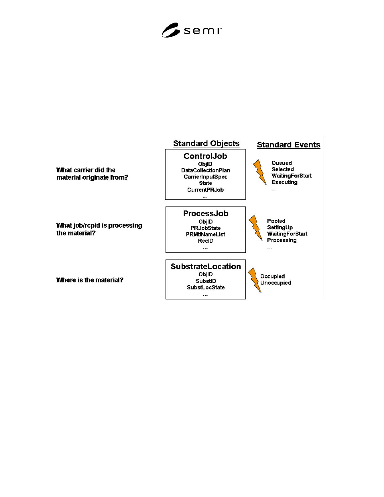
Figure R1-2
SEMI Standard Context Data
R1-1.2.7 Additional context data can be obtained from the SEMI 300mm standards (SEMI E40, SEMI E94, and
SEMI E90 data are shown as examples in Figure R1-2). However, at the time of this writing, some context data is
not available in standard form, yet is often essential for most analysis applications. For example, SEMI E40 does
not provide a means for consumers to determine which sub-recipes might be executing on each module of the
equipment, and does not provide a way for consumers to determine which recipe step is currently being executed on
each sub-recipe. This information is essential for fault detection applications, which need to analyze and apply
limits to process data that may change depending on which recipe step is being executed on which component of the
equipment. Unless and until this information becomes standardized, equipment suppliers will need to provide this
information to applications using proprietary events, exceptions and parameters.
R1-1.2.8 Putting the standards data together with equipment-specific data to cover the gaps, we can see how a
consumer can take an incoming Data Collection Management TraceReport and determine much of the processing
context. A typical example might involve the following high-level steps:
Inspect the self-descriptive information available from the equipment via SEMI E125 to identify the low-level
sensor/actuator and process Parameters from each SEMI E120 equipment component that are of significance to
the purpose of the analysis application (diagnostic, fault detection, etc.)