semi合集-English.pdf - 第6268页
SEMI G52-90 © SEMI 1990, 2004 4 Retentio n Tim e (Min.) 0 5 10 Cation 10 0 5 R e te ntio n T i m e ( M in. ) A nion + 2 – Figure 1 Schematic of Ion Chromatograph NOTICE: SEMI makes no warranties or representations as to …
SEMI G52-90 © SEMI 1990, 2004 3
10.2.2 Place the bags in the water bath at T > 95°C for
30 ± 2 minutes.
10.2.3 Remove the bags from the bath and allow to
reach room temperature.
10.2.4 The lead frames, which are inside the sealed
bags, are moved to one side of the bags without
opening the bags. Then the solution is separated from
leadframes by sealing the mean portion of the bags
without opening.
11 Procedure — Container Extraction Method
NOTE 9: The size of the containers to be used depends on
the expected volume of water and the leadframes. The
container must be at least three-quarters filled with the water
and leadframes.
11.1 Preparation of Extraction Vessels
11.1.1 Fill the containers with DI water and attach the
caps. In order to reduce the amount of air in the vessel,
fill vessels to the amount of three-quarter.
NOTE 10: Two containers are required for each test and must
come from the same manufacturing batch.
11.1.2 Place the containers in the water bath at T >
95°C for 2 hours ± 5 minutes.
11.1.3 Remove the containers from the bath and rinse
out five (5) times with DI water.
11.2 Process
11.2.1 Place the samples in one of the containers
cleaned per Section 11.1.1.
NOTE 11: Leadframes may be cut or rolled in order to ease
loading to the container. Die pads may be tested separately, if
desired, by cutting from the leadframes.
11.2.1.1 Add the required volume of DI water and cap
the container. Place a similar amount of water into the
other cleaned container and attach the cap.
NOTE 12: Do not select the frames or remove them from
their shipping container until ready to test for the surface
contamination. Recommended volumes of water are 10–30 ml
for testing die pads only and 100 ml for the entire leadframe
— samples must be covered by water.
11.2.2 Place the containers in the water bath at T >
95°C for 30 ± 2 minutes.
11.2.3 Remove the containers from the bath and allow
to reach room temperature.
11.2.4 Remove the leadframes from the container and
cap it again.
12 Measurements
12.1 Prepare the chromatograph for operation by
regenerating the columns according to the
manufacturer’s recommendations.
12.2 Run the eluent through the chromatograph until a
stable baseline calibration is established.
12.3 Inject the recommended sample size of test
solution into the chromatograph and record the ion
chromatogram.
12.4 Repeat for all the samples and also run the
background sample.
NOTE 13: The time from extraction to insertion of sample is
to be within eight hours.
12.5 Sample concentrations are determined from the
calibration curves for each ion type.
12.6 The surface concentration of ionic contaminants
for each ion type (SCIC) is given by the following
equation:
SCIC (ng/cm
2
) =
(Sample conc. – Background conc.)
Extraction Volume (mL)
Leadframe Surface Area (cm
2
)
No. of Leadframes
NOTE 14: Allowable concentration levels are to be agreed
between the user and supplier.
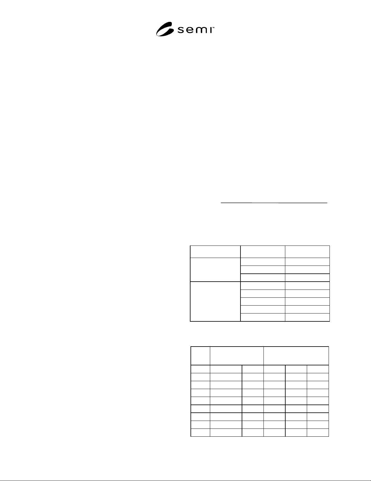
Table 1 Sensitivity of Ion Chromatograph
Ion Sensitivity (ng/ml)
Na
+
0.2
NH
4
+
0.5
Cation
K
+
1.0
Cl
0.3
PO
4
3
2.0
Br
-
1.0
NO
3
-
1.0
Anion
SO
4
2-
1.0
Table 2 Concentration of Standard Solution for
Calibration
Mixed Standard
Solution (ug/ml)
Standard Solution for
Calibration(ng/ml)
Ion I II III
Cation Na
+
10 5 10 20
NH
4
+
10 5 10 20
K
+
10 5 10 20
Anion Cl
4 10 20 40
PO
4
3
10 25 50 100
Br
4 10 20 40
NO
3
4 10 20 40
SO
4
2
4 10 20 40
SEMI G52-90 © SEMI 1990, 2004 4
Retention Time (Min.)
0
5
10
Cation
10
0
5
Retention Time (Min.)
A
nion
+
2
–
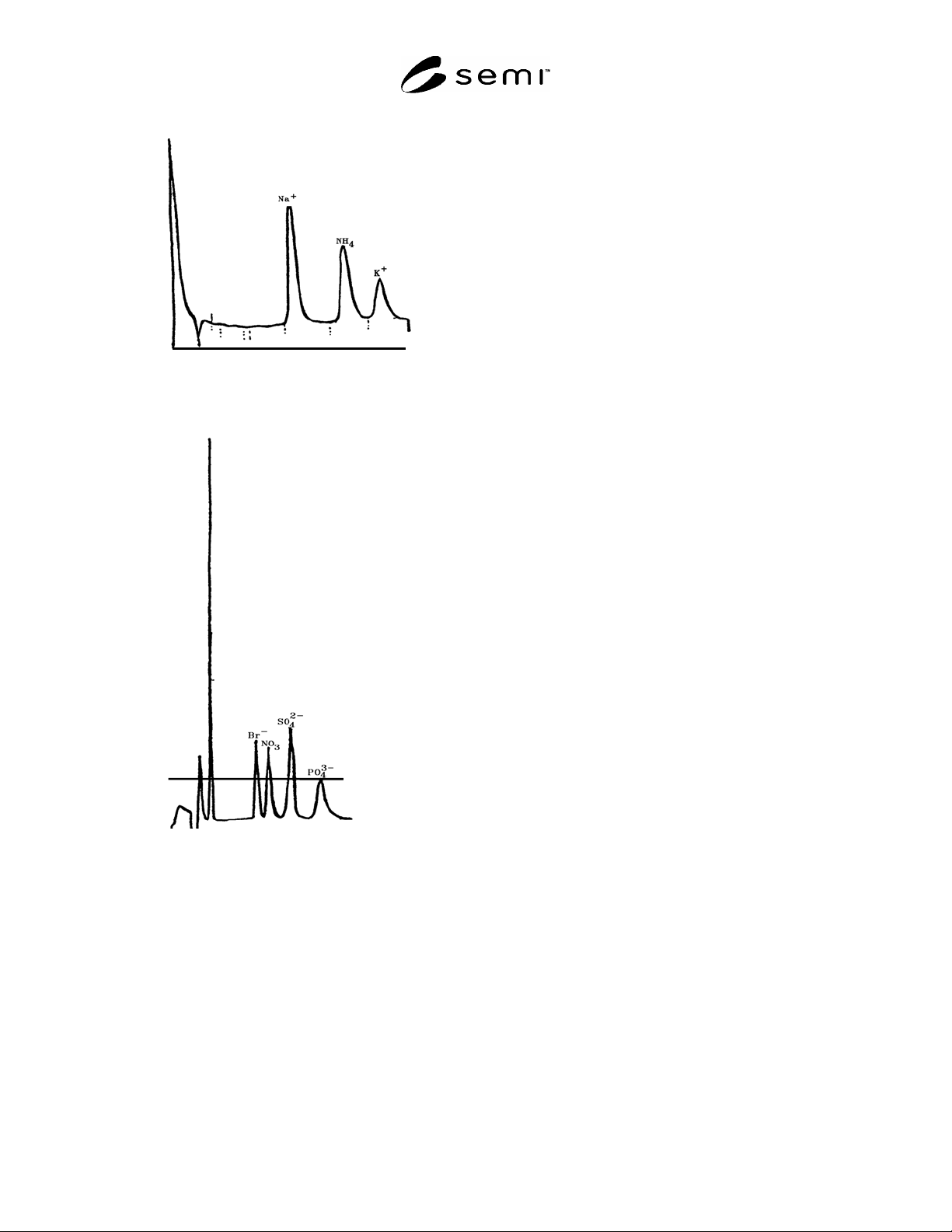
Figure 1
Schematic of Ion Chromatograph
NOTICE: SEMI makes no warranties or
representations as to the suitability of the standards set
forth herein for any particular application. The
determination of the suitability of the standard is solely
the responsibility of the user. Users are cautioned to
refer to manufacturer’s instructions, product labels,
product data sheets, and other relevant literature
respecting any materials mentioned herein. These
standards are subject to change without notice.
The user’s attention is called to the possibility that
compliance with this standard may require use of
copyrighted material or of an invention covered by
patent rights. By publication of this standard, SEMI
takes no position respecting the validity of any patent
rights or copyrights asserted in connection with any
item mentioned in this standard. Users of this standard
are expressly advised that determination of any such
patent rights or copyrights, and the risk of infringement
of such rights, are entirely their own responsibility.
Copyright by SEMI® (Semiconductor Equipment and Materials
International), 3081 Zanker Road, San Jose, CA 95134. Reproduction of
the contents in whole or in part is forbidden without express written
consent of SEMI.

SEMI G53-92 © SEMI 19921
SEMI G53-92
SPECIFICATION FOR METAL LID/PREFORM ASSEMBLY
1 Preface
1.1 Scope — This specification provides guidelines for
the design and acceptance of metal lid/preform
assemblies (see Figure 1). This specification may be
used by suppliers at outgoing inspection and by the
customers at incoming inspection.
The design and acceptance criteria may be used for
metal lid/preform assemblies used on all types of
semiconductor packages.
1.2 Significance — Improper lid/preform design and
poorly specified lid/preforms contributes to low sealing
yields and unreliable devices.
1.3 Units — U.S. Customary (inch -pound) or SI
(metric) units may be used at the customer’s discretion.
This specification uses U.S. Customary units as the
prime unit.
2 Applicable Documents
2.1 Order of Precedence — To avoid conflicts, the
order of precedence when ordering metal lid-preform
assemblies shall be as follows:
Purchase Order
Customer’s Lid-Preform Drawing
This Specification
Reference Documents
Related Documents
2.2 Referenced Documents
2.2.1 Military and Federal Specifications
1
MIL-STD 883 — Test Methods and Procedures for
Microelectronics
MIL-M-38510 — General Specification for
Microcircuits
2.2.2 ANSI Specification
2
Y14.5M — Dimensioning and Tolerancing
2.2.3 ASTM Specification
3
B 568 — Measurement of Coating Thickness by X-Ray
Spectrometry
1 Military Standards, Naval Publications and Form Center, 5801
Tabor Avenue, Philadelphia, PA 19120
2 ANSI, 1430 Broadway, New York, NY 10018
3 American Society of Testing and Materials, 100 Barr Harbor Drive,
West Conshohoken, PA 19428-29597
E 10 — Standard Test Method for Brinell Hardness of
Metallic Materials
E 384 — Standard Test Method for Microhardness of
Materials
E 29 — Practice for Using Significant Digits in Test
Data to Determine Conformance to Specifications
E 1182 — Measurement of Surface Layer Thickness by
Radial Sectioning
3 Definitions
blister — any enclosed localized separation of the
plating from the base material or from another layer of
plating which can be depressed by a sharp instrument.
bow — relative flatness of the preform to the lid after
spot welding.
burr — an adherent fragment of parent material, lid or
preform, at the edge of the lid or preform.
chipout — a region of material which is missing from
the surface or edge of the lid or preform.
contamination — three dimensional alien material
adhering to a surface.
corrosion — electrochemical degradation of the
material usually exhibited by discoloration such as rust.
crack — a cleavage or fracture which extends to the
surface of the lid or through the preform.
discoloration — any change in the color of the plating
as detected by the unaided eye which normally occurs
after the application of heat.
foreign material — an adherent particle other than
parent material of that component.
NOTE: Adherent means inability to be removed with an air or
Nitrogen blow-off at 20 psi.
gouges — mechanically formed depressions in the lid
surface.
nodules — lumps of plating extending above the
surface of the lid.
oil canning — lid concavity after sealing.
peeling — the lifting of plating from a surface.
pit — a hole or depression extending below the surface
of the lid or preform.
preform — a solder material of defined volume that is
attached to the base material.