semi合集-English.pdf - 第3917页
SEMI F32-0998 © SEMI 1998 6 NOTICE: T hese standards do n ot purport to address safety issues, if any, ass o ciated with their use. It is the responsibility of t he user of these standards to establish appropriate safety…
SEMI F32-0998 © SEMI 19985
pressure ratio, and analyzes the data to compute the
choked flow pressure drop ratio, x
T
. This method has
been found, through exhaustive testing, to be a very
accurate and reliable method to determine the
expansion factor, without having to achieve choked
flow in the test valve itself.
10 Pressure Drop Calculation
10.1 The determination of both flow coefficient and
expansion factor are critical in calculating the pressure
drop across a valve flowing compressible fluid. Use of
the flow coefficient C
v
only, will yield a pressure drop
which is lower than the actual value.
10.1.1 Incompressible Flow
10.1.1.1 To calculate pressure drop across a valve
flowing an incompressible media, only the C
v
coefficient must be provided by the valve manufacturer.
The following equation has been derived from
ANSI/ISA-S75.01, Section 4.1, and should be used for
pressure drop computations:
∆P
kPa
= 0.0865*
Q
m
3
hr
C
v
ℜ
ℜ
ℜ
ℜ
ℜ
ℜ
2
× S
f
∆P
psid
=
Q
gpm
C
v
ℜ
ℜ
ℜ
ℜ
ℜ
ℜ
2
× S
f
ℜ
ℜ
ℜ
ℜ
ℜ
ℜ
Equation 2
Pressure Drop for Incompressible Flow
10.1.2 Compressible Flow
10.1.2.1 To calculate pressure drop across a valve
flowing a compressible media, both C
v
and x
T
coefficients may be used to determine more accurately
the pressure drop. Contact the valve manufacturer for
values of C
V
and x
T
coefficients. Equation 3 has been
derived from ANSI/ISA-S75.01, Section 6.1, and
should be used for pressure drop computations.
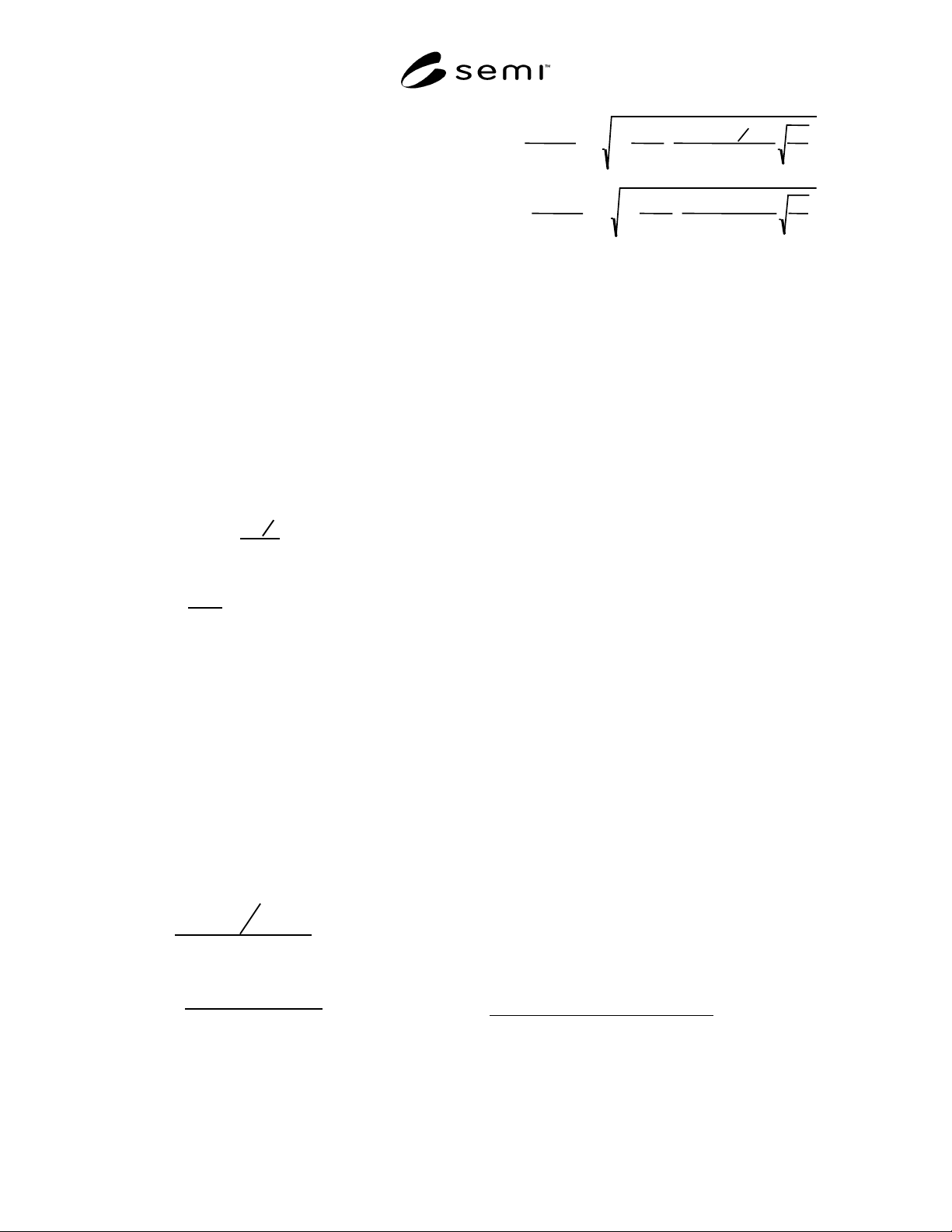
Equation 4 is a close approximation of Equation 3 that
computes pressure drop directly.
∆P
kPa
=
Q
m
3
hr
4.17 × C
v
× Y × P
1kPa
ℜ
ℜ
ℜ
ℜ
ℜ
ℜ
ℜ
2
× S
g
× T
°K
× P
1
KPa
∆P
psid
=
Q
scfh
1360 × C
v
× Y × P
1
psia
ℜ
ℜ
ℜ
ℜ
ℜ
ℜ
2
× S
g
× T
° R
× P
1
psia
ℜ
ℜ
ℜ
ℜ
ℜ
ℜ
Equation 3
Pressure Drop for Compressible Flow – ISA
Iterative Solution
∆
P
=
P
1
kPa
×
x
T
1.125
1 − 1 −
1.125
x
T
S
g
×
Q
m
3
hr
3905.6 ×
C
v
×
P
1
kPa
T
°
K
S
g
ℜ
ℜ
ℜ
ℜ
ℜ
ℜ
2
ℜ
ℜ
ℜ
ℜ
ℜ
ℜ
ℜ
ℜ
∆
P
=
P
1
p
sia
×
x
T
1.125
1 − 1−
1.125
x
T
S
g
×
Q
scfm
16.04 ×
C
v
×
P
1
p
sia
T
°
R
S
g
ℜ
ℜ
ℜ
ℜ
ℜ
ℜ
2
ℜ
ℜ
ℜ
ℜ
ℜ
ℜ
ℜ
ℜ
ℜ
ℜ
ℜ
ℜ
ℜ
ℜ
ℜ
ℜ
Equation 4
Pressure Drop for Compressible Flow – Non-
Iterative Solution
NOTE: The numerical value of x used in these equations must
not exceed the choking limit (x
T
) regardless of the actual
value of x.
11 Related Documents
11.1 ISO Document
2
ISO 6358 — Pneumatic fluid power — Components
using compressible fluids — Determination of flow-rate
characteristics
11.2 SAE Documents
3
ARP 24B — Determination of Hydraulic Pressure Drop
ARP 868 — Pressure Drop Test for Fuel System
Components
2 International Organization for Standardization, Casa Posatale 56,
CH-1211, Geneve 20 , Switzerland
3 Society of Automotive Engineers, World Headquarters, 400
Commonwealth Dr., Warrendale, PA 15096-0001, Telephone:
724.776.4841, Fax: 724.776.5760

SEMI F32-0998 © SEMI 1998 6
NOTICE: These standards do not purport to address
safety issues, if any, associated with their use. It is the
responsibility of the user of these standards to establish
appropriate safety and health practices and determine
the applicability of regulatory limitations prior to use.
SEMI makes no warranties or representations as to the
suitability of the standards set forth herein for any
particular application. The determination of the
suitability of the standard is solely the responsibility of
the user. Users are cautioned to refer to manufacturer’s
instructions, product labels, product data sheets, and
other relevant literature respecting any materials
mentioned herein. These standards are subject to
change without notice.
The user’s attention is called to the possibility that
compliance with this standard may require use of
copyrighted material or of an invention covered by
patent rights. By publication of this standard, SEMI
takes no position respecting the validity of any patent
rights or copyrights asserted in connection with any
item mentioned in this standard. Users of this standard
are expressly advised that determination of any such
patent rights or copyrights, and the risk of infringement
of such rights, are entirely their own responsibility.
Copyright by SEMI® (Semiconductor Equipment and Materials
International), 3081 Zanker Road, San Jose, CA 95134. Reproduction o
f
the contents in whole or in part is forbidden without express written
consent of SEMI.

SEMI F33-0998 © SEMI 19981
SEMI F33-0998
METHOD FOR CALIBRATION OF ATMOSPHERIC PRESSURE
IONIZATION MASS SPECTROMETER (APIMS)
1 Purpose
1.1 This test method may provide guidelines for the
calibration of the APIMS for measurement of
impurities in nitrogen, argon, helium and hydrogen.
APIMS is currently the technique of choice for
measurements of low level impurities in gas
distribution systems and components because it is
essentially the only commercially available method
capable of ppt impurity analysis and it has a superior
response time. This method may provide guidelines for
application of other techniques with similar detection
limits and response time to APIMS which are not
commercially available at this time.
2 Scope
2.1 This method applies to the analyte calibration of
the APIMS for a target impurity range of 100 ppt to as
high as 100 ppb impurity range. The actual calibration
range should bracket the impurity measurement range
of interest, dependent upon the measurement to be
conducted. Anything else is outside the range of the
calibration.
3 Limitations
3.1 The actual range of calibration will depend upon
the type of APIMS used. Counting detection electronics
will saturate in the 200,000 CPS to 1,000,000 CPS
range, depending upon the make and model. Counting
detection will have to use different ions in different
concentration regions, depending upon the impurity.
The actual calibration procedure will be different for
APIMS using analog detection versus counting
detection. Interference between impurities can cause
limitation in measurements in the presence of multiple
impurity species.
4 Referenced Documents
4.1 SEMI Standards
SEMI C9.1 — Guide for Analysis of Uncertainties in
Gravimetrically Prepared Gas Mixtures
SEMI C15 — Test Method for ppm and ppb Humidity
Standards
5 Terminology
5.1 Acronyms
5.1.1 APIMS — Atmospheric Pressure Ionization
Mass Spectrometer
5.1.2 CPS — Counts per second
5.1.3 m/z — m in atomic mass units and z in
elementary charge units
5.1.4 NIST — National Institute of Standards and
Technology
5.1.5 ppb — Molar parts per billion (nmole/mole).
The same as ppbv.
5.1.6 ppm — Molar parts per million (µmole/mole).
The same as ppmv.
5.1.7 ppt — Molar parts per trillion (pimole/mole).
The same as pptv.
5.1.8 R
2
— The statistic described b y the ratio of the
sum of squares of the regression divided by the total
sum of the squares.
5.2 Definitions
5.2.1 zero gas — Nitrogen, argon, helium or hydrogen
with an estimated level an order of magnitude, or more,
lower than the lowest calibration point for each
impurity of interest.
6 Summary of Method
6.1 The calibration of the APIMS is conducted by
adding known concentrations of impurities to a zero gas
and measuring the corresponding ion intensities. A
calibration response factor can be determined by
regression analysis.
7 Interferences
7.1 It is essential to confirm that the mass chosen is
indeed representative of the species of interest and that
other commonly present impurities do not contribute at
the same mass. For example: the intensity of the peak at
m/z = 29 correlates with the concentration of H
2
in N
2
,
because of the N
2
H
+
formation. However, spurious
signal at this peak can arise in two different ways:
(i) Contributions of other ions of the same mass, such
as N
14
N
15+
or C
2
H
5
+
.
(ii) Contributions of the same ion from different parent
species, i.e., N
2
H
+
due to recombination of matrix
gas nitrogen with fragments of H
2
O, CH
4
, etc.
Before using m/z = 29 as a measure of H
2
in N
2
,
interference such as these must be understood. This
also may apply to other ions.