semi合集-English.pdf - 第2058页
SEMI E54.10-0600 © SEMI 2000 3 Data Item Description Range 1/1/72 (UINT ) 7 Conventions 7.1 This docum ent embraces the c o n ve ntions a nd notati ons stat ed in Section 6 of SEMI E54.1 [3]. 8 Device High L evel St ruct…

SEMI E54.10-0600 © SEMI 2000 2
intended for higher level applications and thus are not
applied to the In-Situ Particle Monitor Device Model.
3.5 Operation over the entire range specified for an
attribute within a specific object is not a requisite for
compliance with this specification.
4 Referenced Standards
4.1 SEMI Standards
SEMI E39 — Object Services Standard: Concepts,
Behavior, and Services
SEMI E54 — Sensor/Actuator Network Standard
SEMI E54.1 — Standard for Sensor/Actuator Network
Common Device Model
NOTE 1: As listed or revised, all documents cited shall be the
latest publications of adopted standards.
5 Terminology
5.1 Abbreviations and Acronyms
5.1.1 LCS — an ISPM sensor named the Laser Current
Sensor.
5.1.2 MNS — an ISPM sensor named the Median
Noise Sensor.
5.1.3 SLS — an ISPM sensor named the Stray Light
Sensor.
5.2 Terminology Defined in This Document
5.2.1 In-Situ Particle Monitor (ISPM) — a self-con-
tained device, consisting of a laser that generates light,
a light detector, counters, diagnostics and control and
signal-processing electronics, commonly used in the
semiconductor industry to measure and count particles
in a specific area.
5.3 This document inherits the terminology defined by
SEMI E54.1 [3].
5.3.1 Attribute
5.3.2 Behavior
5.3.3 Boolean
5.3.4 Byte
5.3.5 Character
5.3.6 Common Device Model (CDM)
5.3.7 Data Type
5.3.8 Data Units
5.3.9 Device
5.3.10 Device Manager (DM) Object
5.3.11 Device Model
5.3.12 Double Integer (DINT)
5.3.13 Enumerated Byte
5.3.14 Full Scale Range
5.3.15 Instance
5.3.16 Last Valid Value (LVV)
5.3.17 Long Integer (LINT)
5.3.18 Long Real (LREAL)
5.3.19 Manufacturer
5.3.20 Nibble
5.3.21 Null Character
5.3.22 Object
5.3.23 Real (REAL)
5.3.24 S, A, and C Objects
5.3.25 Sensor Actuator Controller (SA C) Object
5.3.26 Service
5.3.27 Short Integer (SINT)
5.3.28 Signed Integer (INT)
5.3.29 State Diagram
5.3.30 Test String
5.3.31 Unsigned Double Integer (UDINT)
5.3.32 Unsigned Double Long Integer (UDLINT)
5.3.33 Unsigned Integer (UINT)
5.3.34 Unsigned Long Integer (ULINT)
5.3.35 Unsigned Short Integer (USINT)
6 Requirements and Specifications
6.1 In order to implement this standard in an In-Situ
Particle Monitor Device, it is necessary to also
implement SEMI E54.1 and one of the Sensor/Actuator
Network Communication Standards [2]. See Section 1.1
for more information on a complete interoperability
standard.
6.2 This specification also requires the implementation
of a Date_And_Time data structure used to represent
the current device Date and Time. Table 1 defines the
format of the Date_And_Time data type.
Table 1 Date_And_Time Format
Data Item Description Range
1 Number of milli-seconds
since midnight
Unsigned Double
Integer (UDINT)
2 Number of days since Unsigned Integer
SEMI E54.10-0600 © SEMI 20003
Data Item Description Range
1/1/72 (UINT)
7 Conventions
7.1 This document embraces the conventions and
notations stated in Section 6 of SEMI E54.1 [3].
8 Device High Level Structu re
8.1 General Description
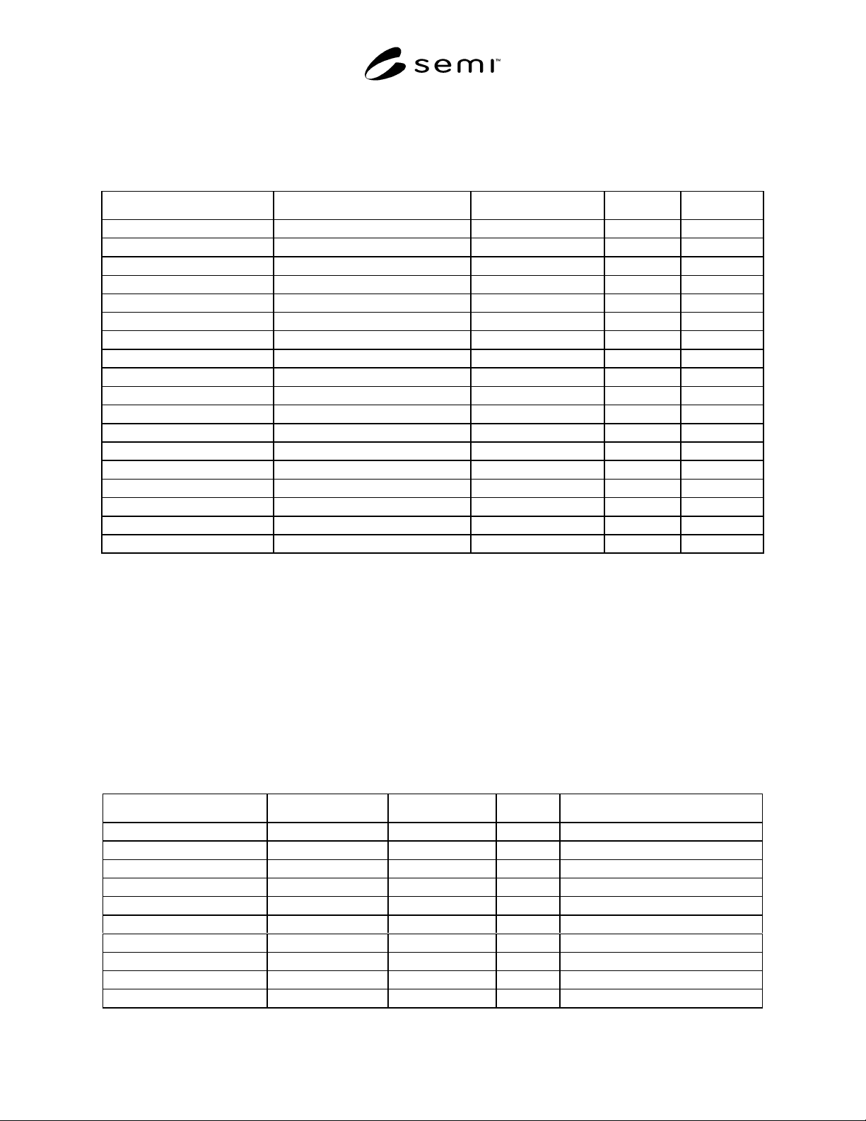
8.1.1 The high-level object view of an In-Situ Particle
Monitor (ISPM) Device is shown in Figure 1.
8.1.2 Note that the “ISPM” device object is depicted
in Figure 1 only for the purposes of illustrating a high
level view of the device and its component objects. In
the context of this document, this object is not
addressable, does not have addressable attributes, does
not have accessible services, and does not exhibit any
defined behavior.
8.1.3 In the remainder of this section, this document
defines in detail all of the component objects unique to
the ISPM device. References, rather than definitions,
are included for the DM, the SAC, and other objects
defined in SEMI E54.1 [3].
8.1.4 Many of the objects defined in this document
inherit properties from other objects. The properties
inherited include attribute, services, and behavior
definitions. These other objects are specified here or in
SEMI E54.1 [3].
8.1.5 This document provides for future extensions as
well as manufacturer specific enhancements by
reserving object attribute identifiers and object service
identifiers. Specifically, all object definitions in this
document specify or reserve the first 64 attribute
identifiers (A1 through A64) and the first 64 service
identifiers (S1 through S64) allowing manufacturers to
specify identifiers beyond these ranges. Additionally,
byte enumerated attributes are specified or reserved
from 0 to 63 allowing manufacturers to specify an
enumeration beyond this range (64 to 255).
8.1.6 In-Situ Particle Monitor (ISPM) Device
Description
8.1.6.1 An In-Situ particle Monitor device profile is
composed of the component objects and object
relationships shown in Figure 1.
1+
ISPM Device
Sensor-AI-LCS
Reading Valid
Full Scale
Alarm Settling Time
Warning Settling Time
Sensor-AI
(defined in CDM)
Sensor-AI-SLS
Reading Valid
Full Scale
Alarm Settling Time
Warning Settling Time
Sensor-AI-MNS
Reading Valid
Full Scale
Alarm Settling Time
Warning Settling Time
SAC (See NOTE 1)
Number of Bins
Count Mode
Duration
-----------
Clear Counts
DM (See NOTE 1)
Gain
Filter Bandwidth
Tool State
Laser Status
Flow Path
Volume
Volume Units
Leak Status
Time Stamp
----------------
Laser On
Laser Off
Assembly
(defined in CDM)
Assembly-ISPM #1
Sensor-AI-Counter
Reading Valid
Full Scale
Alarm Settling Time
Warning Settling Time
Upper Size
Low Size
Assembly-ISPM #2
Assembly-ISPM #9
•
•
•
Assembly-ISPM #48
(See
NOTE
2)
NOTE 1: The DM and SAC are taken from the CDM. Additional attributes and services are added to support the ISPM device.
NOTE 2: Assembly-ISPM #1 and Assembly-ISPM #6 objects are required. Other Assembly-ISPM objects are optional.
Figure 1
In-Situ Particle Monitor Device High Level Structure
SEMI E54.10-0600 © SEMI 2000 4
8.1.7 General Requirements
8.1.7.1 Device Objects — All objects are defined in terms of their object name and Class/Object identifier.
Identifiers for all objects described in this document are summarized in Table 2.
Table 2 In-Situ Particle Monitor Device Objects
Referenced Document Section Object Name Class/Object Identifier Minimum # Maximum #
8.2 Device Manager (DM) ISPMD1 1 1
8.3 Sensor Actuator Controller (SAC) ISPMD2 1 1
8.5 Sensor-AI-LCS ISPMD3 0 1
8.6 Sensor-AI-SLS ISPMD4 0 1
8.7 Sensor-AI-MNS ISPMD5 0 1
8.8 Sensor-AI-Counter ISPMD16 1 1024
8.9 Assembly-ISPM#1 ISPMD17 1 1
8.9 Assembly-ISPM#2 ISPMD18 0 1
8.9 Assembly-ISPM#3 ISPMD19 0 1
8.9 Assembly-ISPM#4 ISPMD20 0 1
8.9 Assembly-ISPM#5 ISPMD21 0 1
8.9 Assembly-ISPM#6 ISPMD22 1 1
8.9 Assembly-ISPM#7 ISPMD23 0 1
8.9 Assembly-ISPM#8 ISPMD24 0 1
8.9 Assembly-ISPM#9 ISPMD25 0 1
8.9 Assembly-ISPM#48 ISPMD64 0 1
— Reserved ISPM26–ISPM63 — —
— Manufacturer Specified > ISPM64 — —
8.1.7.2 Object Services — Not all object services listed in this document can necessarily be requested over the
network. They are included in this document because their behavior may generate network activity.
8.1.7.3 Object Behavior — For all service requests received over the network that are not supported by the object,
or contain a parameter value which is beyond the supported range, or which is otherwise invalid, a network specific
service error response is generated.
8.2 Device Manager Object (DM) — The Device Manager object is the device component responsible for
managing and consolidating the device operation as specified in SEMI E54.1 [3]. The following sections specify the
components of the DM object that are not specified in SEMI E54.1 or require further definition than specified in
SEMI E54.1.
8.2.1 Device Manager Object Attributes — Required and optional DM object attributes are listed in Table 3.
Table 3 DM Object Attributes
Attribute Name Attribute Identifier Access Network Required Form
Device Type A1 R Yes refer to CDM [1]
Exception Detail Alarm A13 R No refer to CDM [1]
Exception Detail Warning A14 R No refer to CDM [1]
Gain A33 RW * No REAL
Filter Bandwidth A34 RW * No REAL
Tool State A35 R No USINT, enumerated
Laser Status A36 R Yes USINT, enumerated
Flow Path A37 RW No USINT
Volume A38 R No REAL
Volume Units A39 R No Byte, enumerated