semi合集-English.pdf - 第3909页
SEMI F31-0698 © SEMI 1998 3 incorporates all of th e physical act ivities and testing paramet er s and est ablishes check poi nts for approvals at each stage. 6.3 Acceptance Tes ts — Acceptan c e test s are conducted on …

SEMI F31-0698 © SEMI 1998 2
chemical until it is transferred to the manufacturing
process.
5.2.6 decontamination — Cleaning up of a BCD
System, or any subsystems thereof, by introducing
chemical solutions into the piping systems. This
procedure occurs during qualification and prior to
commissioning the system.
5.2.7 dilution — Combination of a concentrated
chemical and DIW to create a lower concentration of
the aqueous chemical.
5.2.8 on-site gas-to-chemical generation — The
contacting of a liquid and gas phase to create a stable
liquid solution. The chemical is generated on-site in a
form suitable for distribution through a dispense
system.
5.2.9 pickling — Conditioning of the system by filling
it with the actual chemical or another chemical for
which the system is designed. This chemical will stay in
the system for a specified period of time. The purpose
of this conditioning is to leach out impurities prior to
actually using any chemical in the manufacturing
process.
5.2.10 polishing — The process of flowing chemical
through a filter one or more times to reduce the
particulate levels of the chemical.
5.2.11 primary containment — Tubing, piping, or
components whose wetted surface is directly in contact
with the chemical. These components are generally
made from fluoropolymer materials such as
Perfluoroalkoxy (PFA).
5.2.12 secondary containment — Tubing or piping
which contains the primary piping or tubing. The
purpose of this configuration is to control leaks and to
protect against spills. Secondary containment of solvent
systems generally uses stainless steel material, and acid
or base systems generally use Schedule 40
Polyvinylchloride (PVC) material boxes such as VMB.
This may also be used as secondary containment.
5.2.13 stabilized filtration — A design feature that
provides for the continuous flow of chemical through
filters to minimize shocking and pulsating of the filters.
5.2.14 surge suppression — Use of a device or in-line
chamber that minimizes flow pulsations caused by a
pump. This may also be referred to as pulsation
dampener.
5.2.15 valve manifold box (VMB) — A chemical-
resistant enclosure which houses manual and/or
pnuematically actuated valves, tees, and fittings.
5.2.16 vessel — A vessel fabricated from or
containing an inner lining of chemically inert and
resistant materials which is specifically designed to
maintain the purity level of the chemical for a long
period of time. All containers are fabricated from or at
least contain an inner lining of chemically inert and
resistant materials and are specifically designed to
maintain the purity level of the chemical for long
periods of time. The larger containers are generally
designed in conformance to Department of
Transportation Regulations (DOT) and may be
transported by ground. These containers have fittings
which are compatible to this purpose so that they may
be hooked up to the BCD Systems directly. Such
containers include:
5.2.16.1 drum — A container for storing chemicals,
generally with a cylindrical shape and not more than 55
gallons or 200 liters in size.
5.2.16.2 tote — A container for storing chemicals,
generally 110, 220, or 330 gallons in size and requiring
an outer shell to provide structural support to the vessel.
5.2.16.3 ISO container — A container for storing
chemicals, usually large in size, able to be transported
directly, and designed in compliance with criteria from
the International Standards Organization.
5.2.17 wetted surface — Any surface which comes
into contact with the chemical.
6 General Requirements
6.1 Materials — Components of the BCD Systems
must be appropriate to the application and conform to
electrical, mechanical, and chemical requirements as
defined by the physical installation environment, local
and national code interpretations, process requirements,
and delivery specifications.
6.2 System Installation — The Bulk Chemical
Distribution System is installed according to a protocol
which ensures mechanical integrity, leakproof
operation, and minimal contamination to any liquids
being distributed throughout the system.
6.2.1 System Installation procedures include a
rinsedown protocol which may include any of the
following: (1) a flushing procedure with DIW; (2) a
sanitization step using hydrogen peroxide; (3) a drying
step using nitrogen gas; and (4) a “pickling” process
using the actual chemical, or a less concentrated form
of the chemical. For solvent systems, the rinse-down
chemicals introduced are generally the same as the
solvent that is designated to be used in the system,
whereas for acid systems, the rinse down solutions may
include DIW, ozonated water, or a dilute form of
hydrogen peroxide.
6.2.2 The protocol for System Installation and start-up
follows a predefined sequence of events which
SEMI F31-0698 © SEMI 19983
incorporates all of the physical activities and testing
parameters and establishes check points for approvals at
each stage.
6.3 Acceptance Tests — Acceptance tests are
conducted on each subsystem or system produced. They
are the basis for acceptance or rejection by the
purchaser.
6.3.1 Acceptance testing may include performance
demonstrations, demonstration of reliability criteria,
and achievement of purity standards. Safety
considerations are addressed elsewhere.
6.4 Qualification Testing — Qualification testing is
performed on the liquid chemicals being transported
through each chemical piping subsystem.
6.4.1 Qualification testing may include tests for trace
metals, anions, particles, and total organic carbon.
Assay analysis is recommended for blending or dilution
operations.
6.5 Chemical Specifications — Particulate BCD
Systems are specified as to the level of impurities at the
point of use as compared to the quality of the incoming
chemical. Impurities in the chemical are generally
specified in terms of particles per ml; metallic
impurities are specified for each element and for total
adders; and organic impurities are specified for total
added.
7 Basic Design Elements
7.1 General — Each Bulk Chemical Distribution
System contains certain basic components and a variety
of design options to meet particular customer and
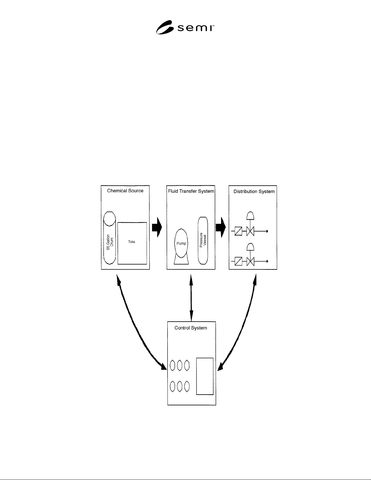
facility needs. A simple example system is shown in
Figure 1.
Figure 1
Schematic of Basic Bulk Chemical Distribution System

SEMI F31-0698 © SEMI 1998 4
7.2 Source — The source of all fluids for incoming
Bulk Chemical Distribution Systems is a container
suitable for holding reactive chemicals in a size 55
gallons or greater, which may include drums, totes,
vessels, or ISO containers.
7.3 Fluid Transfer — Fluids in the Bulk Chemical
Distribution Systems are transported through pipes
using either a pumping system, a pressure differential
system, or some combination of the two types of basic
systems. All fluids are transported in secondary
containment piping systems for safety reasons.
7.4 Distribution — The transfer is made from the
source by means of certain types of mechanisms,
usually through one or more valve manifold boxes, that
direct the fluid to a point of use, to subordinate levels of
distribution, and/or to a day tank.
7.5 Control Systems — Manual and/or automated
mechanical, pneumatic, hydraulic, optical, and
electronic systems control the movement of the liquids.
This includes the volume, flow rate, pressure, start-up,
and shut-off.
8 Optional Design Features
8.1 Polishing — BCD Systems ma y be designed with
the possibility of chemical recirculation (1) from the
incoming source and back, to polish the incoming
chemical; (2) from the day tank and back for further
polishing or timed recirculation if activity is limited;
and (3) fabwide in continuous recirculation.
8.2 Filtration — Chemicals in the system may be
recirculated through filters placed on-line in the system.
The relevant design issues include types of filters,
efficiency, useful lifetime, qualification, filter bleed,
removal, and replacement.
8.3 Day Tank — The vessel that generally stores a
limited amount of chemical volume generally
equivalent to that used in about one day of operation.
This holding vessel usually stores prefiltered chemical
before it is transferred to the manufacturing process.
8.4 Blending — Certain chemicals in distribution are
blended together for use in the semiconductor
manufacturing process. For example, Buffered Oxide
Etchant is a blend of Hydrofluoric Acid and
Ammonium Fluoride and may be sourced as two
separate chemicals and blended together in the correct
concentrations within the BCD Systems.
8.5 Dilution — Certain chemicals used in the
semiconductor manufacturing process require various
concentrations, depending on the process used at a
particular point in the system. For example, 49%
Hydrofluoric Acid is brought in as the source chemical
and then mixed with DIW in a blend unit to achieve
various concentrations of 10:1, 100:1, etc., depending
on the requirements of the manufacturing process.
8.6 Automated Control Systems — Electronic systems
may be programmed to control system parameters such
as volume, pressure, fill rate, flow, drain times,
maintenance diagnostics, purge cycles, recirculation,
and bypass.
8.7 Sampling Ports — Sampling ports may be
incorporated into the system to facilitate chemical
sampling for qualification and monitoring programs.
8.8 On-Site Chemical Generation — Liquid
chemicals, such as Ammonium Hydroxide, may be
generated on-site at the required concentration from a
clean Ammonia gas source and DIW to the required
concentration. Generally, this activity is done in a
location apart from the dispense room. The resulting
chemical is used as a source for the distribution system.
8.9 Reprocessing — Integrated with the general
chemical distribution system may be a chemical
reprocessing unit which purifies or recycles a chemical
such as sulfuric acid, isopropanol, or hydrofluoric acid.
Such a system enables the chemical to reenter the
system as a clean source of material for manufacturing
processing.
8.10 Stabilized Filtration — Some systems include a
design feature that provides for the continuous flow of
chemical over filters to minimize shocking and
pulsating of the filters.
8.11 Surge Suppression — Some systems include a
device or in-line chamber that minimizes hydraulic
forces caused by a pump. This option may also be
referred to as pulsation dampener.
9 Monitoring and Maintenance of Systems
9.1 General Considerations — Bulk Chemical
Distribution Systems may require a significant level of
maintenance and monitoring to determine that
specifications and performance are initially and
continually met.
9.2 Functional Management System — The entire
dispense system can be monitored by means of
PC/PLC/ or any hybrid system, recording events as they
occur and alerting operators as necessary to take
corrective action. Monitoring systems may include a
variety of operational parameters:
9.2.1 on-line real-time monitoring of all chemical
dispense units
9.2.2 status of components and subsystems
9.2.3 events logging