semi合集-English.pdf - 第1444页
SEMI 30.1-0200 © SEMI 1998, 2000 19 Variab le Name Type Descripti on Level Class Forma t Comment SlotList CV The list of carrier slots with substra tes to be proces sed. ALL DVVAL L,n 1. <SlotID> : n. Substrate Ano…
SEMI 30.1-0200 © SEMI 1998, 2000 18
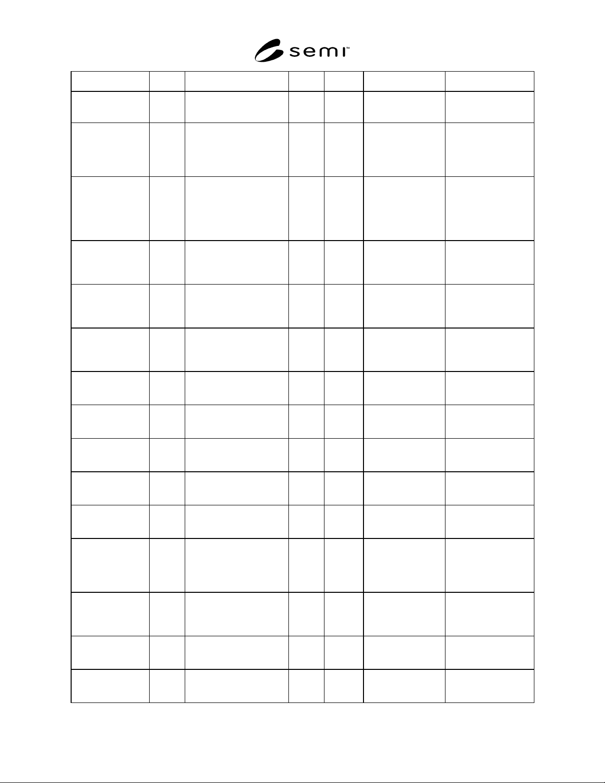
Variable Name Type Description Level Class Format Comment
current material
immediately prior to the
inspection/review.
the ISEM Tables. (See
Section 11.)
ProcessEquipmentLo
cation
CV Location (code) of the
process equipment used
with the current material
immediately prior to the
inspection/review.
ALL DVVAL A[1..16] This information may
be added by the host in
the ISEM Tables. (See
Section 11.)
ProcessEquipmentP
PID
CV Identification of the process
program used with the
process equipment used on
the current material
immediately prior to the
inspection/review.
ALL DVVAL A[1..80] This information may
be added by the host in
the ISEM Tables. (See
Section 11.)
ProcessLevel CV Identification of the
processing level of the
current material.
ALL DVVAL A[1..16] This information may
be added by the host in
the ISEM Tables. (See
Section 11.)
ProcessRunID CV Run identification for the
process prior to current
inspection/review.
ALL DVVAL A[1..16] This information may
be added by the host in
the ISEM Tables. (See
Section 11.)
ProductID CV The product identification
of the current material
inspected/reviewed.
ALL DVVAL A[1..16] This information may
be added by the host in
the ISEM Tables. (See
Section 11.)
RegionComment CV Operator-generated
comment associated with
the region.
X DVVAL A[1..80]
RunAnomaly-Count ISV Total number of all
anomalies found on all
substrates in the last run.
R DVVAL U2
RunComment CV Operator-generated
comment associated with
the run.
ALL DVVAL A[1..80]
RunInspected-
AreasCount
ISV The total number of
inspected/reviewed areas on
all substrates in the last run.
RS DVVAL U2
RunInspection-
PPCount
ISV The total number of process
programs used for the
current or last run.
RS DVVAL U2
RunSubstrate-Count CV The total number of
substrates completed in the
current inspection run,
which remains valid until
the next START command.
ALL DVVAL U2
ScaleFactor CV A correction factor applied
to the translation of one
coordinate system to
another.
ALL DVVAL F4 In most cases, a scaling
of 1 (one) is expected.
SiteID CV Inspection/Review group
identification for the current
site inspection/review.
ALL DVVAL U2
SlotID CV Carrier slot number from
which the current substrate
was taken.
ALL DVVAL U2
SEMI 30.1-0200 © SEMI 1998, 200019
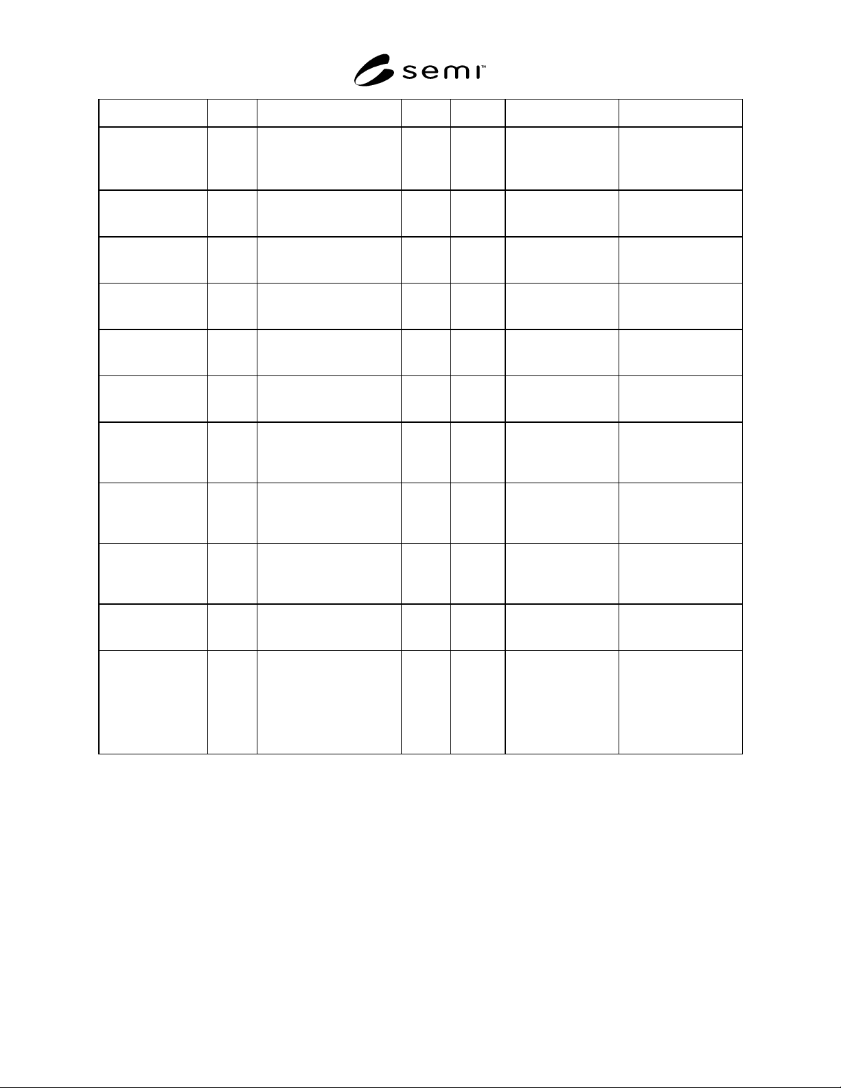
Variable Name Type Description Level Class Format Comment
SlotList CV The list of carrier slots with
substrates to be processed.
ALL DVVAL L,n
1. <SlotID>
:
n.
SubstrateAnomalyC
ount
ISV The total number of
anomalies for the current
substrate.
S DVVAL U2 For the most recent
inspection.
Substrate-Comment CV Operator-generated
comment associated with
the substrate.
ALL DVVAL A[1..80]
SubstrateID CV Substrate identification for
the current
inspection/review.
ALL DVVAL A[1..16]
Substrate-
InspectedAreas-
Count
ISV The total number of
inspected areas on the
current substrate.
S DVVAL U2
SubstrateRegion-
Count
CV Total area count for the
current or last substrate
inspected.
ALL DVVAL U2
SubstrateSize CV The nominal diameter (in
mm) of the current or last
substrate
inspected/reviewed.
ALL DVVAL U2
SubstrateTotal-
AreaInspected
ISV Total square area
inspected/reviewed
(micron
2
) of the current
substrate.
S DVVAL F4
Theta CV The rotational difference in
radians between a primary
and secondary coordinate
system.
ALL DVVAL F4
Tile CV The layout of the pattern in
the substrate.
ALL DVVAL A[1..16] “NTILE” non-tiled,
“CTILE” column-tiled,
and “RTILE” row-tiled.
XLateData CV Variable for the equipment
to report offset of the found
or actual pattern-based
coordinate system relative
to the substrate-based
coordinate system on the
substrate being tested.
ALL DVVAL L,4
1. <DeltaX>
2. <DeltaY>
3. <Theta>
4. <ScaleFactor>
10 Alarm List
Since each model of equipment differs in configuration,
it is not practical to provide an exhaustive list of all
possible alarms. Instead, the ISEM is requiring the two
tables provided as described in SEMI E30 (document
section). Alarm List Table, which is intended to provide
for equipment configuration-specific alarms and Alarm
ID, Alarm Set/Cleared Event Table.
10.1 Alarm List Table
10.1.1 The alarm list table contains examples of
alarms that pertain to various configuration aspects of
equipment. These examples are intended to illustrate
that alarms pertain to situations in which there exists a
potential for exceeding physical safety limits associated
with people, equipment, and material being processed
as per the SEMI E30 definition of an alarm. (See SEMI
E30 for further reference.)
10.2 Alarm ID, Alarm Set/Cleared Event Table
10.2.1 The Alarm ID, Alarm Set/Cleared Event Table
documents the association of each ALID to a set and
cleared event as required by SEMI E30. (See SEMI E30
for further reference.)
SEMI 30.1-0200 © SEMI 1998, 2000 20
11 ISEM Tables
A fundamental requirement of ISEM equipment is to
transfer anomaly and review data between itself and the
host. ISEM equipment may also be required to transfer
“Area” and “Alignment Site” data needed for run setup.
Anomaly and review data sets (as well as area and
alignment site data sets) are commonly handled as lists
and tables. ISEM equipment shall use tables when
transferring this kind of data between itself and the
host. List shall be used to refer to sub-sets of this table
data.
11.1 ISEM Table Data
11.1.1 ISEM Tables are used to specify area, align-
ment site, and anomaly coordinate lists for ISEM equip-
ment. ISEM Tables are transferred between the host
and the equipment using SECS-II Stream 13 messages
(Unformatted Data Set Transfers). For example, an
ISEM Table may be used to transfer anomaly data (e.g.,
“M21” coordinates) generated by inspection equipment
to the host, which in turn may then be transferred to
review equipment from the host. ISEM Tables also
include attributes items that are associated with the
table, not with the table data. ISEM Table attributes are
used to include information associated with table data,
like the number of columns (NumCols), number of
rows (NumRows), and table size (DataLength). (See
SEMI E58 for additional information.) Product or
process-related information may also be included on the
attribute section of the ISEM Tables (e.g., LotID, Pro-
ductID, OperatorID, ProcessEquipmentID) (see Table
4). The ISEM does not specify additional table attribute
variable items that may be associated with the table.
11.2 TABLE-DEFs
11.2.1 ISEM Tables are documented using TABLE-
DEF structures (Figure 5). Each TABLE-DEF structure
has a unique name (TableID) and type (TableType).
Each column in the TABLE-DEF has a name (e.g.,
“AREANAME”, “ALIGNNAME”, OR “ANOM-
ALYID”); row names are specific instances or values
that correspond to the column headers in TABLE-DEF.
A specific TABLE-DEF row is designated by referring
to the TABLE-DEF name and the specific row name.
ISEM Tables are transferred using standard (SECS-II
message) Stream 13 messages (Figure 6), and each
ISEM-defined TABLE-DEF item maps into a Stream
13 message item. Align and area data tables are host-
defined, and anomaly tables are equipment-defined.
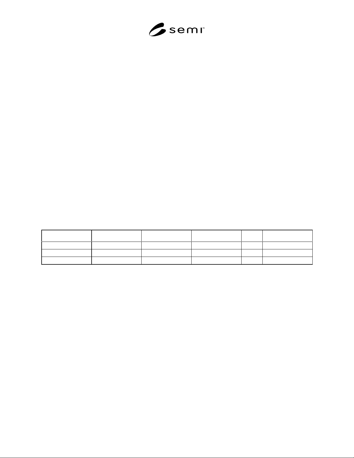
TableType = <TableDef>TableID = <TableName>
Row Name Column
1
Column
2
Column
3
… Column
n
Row
1
Name
…
Row
m
Name
Figure 5
TABLE-DEF Structure