semi合集-English.pdf - 第3913页
SEMI F32-0998 © SEMI 1998 2 5.1.17 x — Ratio of pres sure drop to a bso lute inlet pressure, dim e nsionless, wh ere: x = ∆ P kPa P 1 kPa x = ∆ P psid P 1 psia ℜ ℜ ℜ ℜ ℜ ℜ 5.1.18 x T — Rati o of pressure drop to a bsol…

SEMI F32-0998 © SEMI 19981
SEMI F32-0998
TEST METHOD FOR DETERMINATION OF FLOW COEFFICIENT FOR
HIGH PURITY SHUTOFF VALVES
1 Purpose
1.1 This test method describes how to determine two
criteria used in selecting valves of appropriate size for
gases and liquids.
1.2 Methods and equations are spe cified and/or
referenced to assist in accurate calculation of pressure
drops across valves tested by this method.
2 Scope
2.1 This method establishes the te sting criteria for
determination of two coefficients specified in
ANSI/ISA-S75.02:
• Valve flow coefficient (C
v
)
• Critical pressure drop ratio factor (x
T
)
2.2 This method is to be used with ANSI/ISA-S75.02.
This method applies to manual and actuated valves for
use in both gas and liquid distribution systems used in
semiconductor manufacturing facilities. It is a test
method, where existing test methods are referenced and
limitations are imposed on test conditions. Specific
equations for calculating flow coefficients, choked flow
parameters, and pressure drops are referenced to the
appropriate ISA section.
3 Limitations
3.1 This method will limit the use and interpretation of
ANSI/ISA-S75.02 for use by manufacturers and users
of valves designed for the semiconductor industry.
3.2 This method is not intended to be used to
determine flow coefficients for valves used in vacuum
service.
4 Referenced Documents
NOTE: As listed or revised, all documents cited shall be the
latest publications of adopted standards.
4.1 ANSI Documents
1
ANSI/API 2530 — Part 2: Natural Gas Fluids
Measurement - Concentric, Square-Edged Orifice Met
ANSI/ISA-S-75.01 — Flow Equations for Sizing
Control Valves
1 American National Standards Institute, 11 West 42nd St., New
York, NY 10036, Telephone: 212.642.4900, Fax: 212.398.0023
ANSI/ISA-S75.02 — Control Valve Capacity Test
Procedure
5 Terminology
5.1 Acronyms
5.1.1 ∆P — Pressure drop across va lve, kPa (psi).
5.1.2 F
k
— Ratio of specific heats factor, where:
F
k
=
k
1.40
5.1.3 F
L
— Liquid pressure recovery factor
F
L
=
Q
max
m
3
nr
0.0865 *
C
v
*
P
1
kPa
−
0.96*
P
v
kPa
S
f
F
L
=
Q
max
g
pm
1.00 *
C
v
*
P
1
p
sia
−
0.96*
P
v
p
sia
S
f
ℜ
ℜ
ℜ
ℜ
ℜ
ℜ
ℜ
ℜ
ℜ
ℜ
5.1.4 gpm — Gallons per minute
5.1.5 k — Specific heat ratio
5.1.6 P
1
— Absolute pressure at upstream pressure
tap, kPa (psi).
5.1.7 P
2
— Absolute pressure at downstream pressure
tap, kPa (psi).
5.1.8 P
v
— Absolute vapor pressure of liquid at inlet
temperature, kPa (psi).
5.1.9 psia — Pounds per square inch absolute
5.1.10 psid — Pounds per square inch differential
5.1.11 Q — Volumetric flow rate
5.1.12 Q
max
— Maximum flow rate (c hoked flow
conditions) at a given upstream condition.
5.1.13 scfh — Standard cubic feet per hour
5.1.14 S
f
— Specific gravity of a liqu id relative to
water.
5.1.15 S
g
— Specific gravity of a gas relative to air.
5.1.16 T — Absolute temperature of t est gas or liquid,
°K (°R).
SEMI F32-0998 © SEMI 1998 2
5.1.17 x — Ratio of pressure drop to absolute inlet
pressure, dimensionless, where:
x =
∆P
kPa
P
1
kPa
x =
∆P
psid
P
1
psia
ℜ
ℜ
ℜ
ℜ
ℜ
ℜ
5.1.18 x
T
— Ratio of pressure drop to absolute inlet
pressure (
∆
p/p
1
) at choked flow condition,
dimensionless.
5.1.19 Y — Expansion factor for compressible fluids,
where:
Y =1 −
x
3 × F
k
× x
T
5.2 Definitions
5.2.1 flow coefficient C
v
— A numer ic constant used
to characterize the flow capacity of a valve.
5.2.2 vapor pressure condensation point — Pressure
at which fluid phase changes from liquid to gas, for a
given upstream condition.
5.2.3 vena contracta — Point in a duct where the
diameter of the fluid stream is smaller than the diameter
of the duct.
6 Test Fluids
6.1 Incompressible (Liquid) Fluid — Water is the
standard liquid test fluid.
6.2 Compressible (Gaseous) Fluid — Nitrogen is the
standard gaseous test fluid. When using Nitrogen, care
should be taken to assure that the fluid does not
approach the vapor pressure condensation point at the
vena contracta.
7 Test Setup
7.1 Test Valve
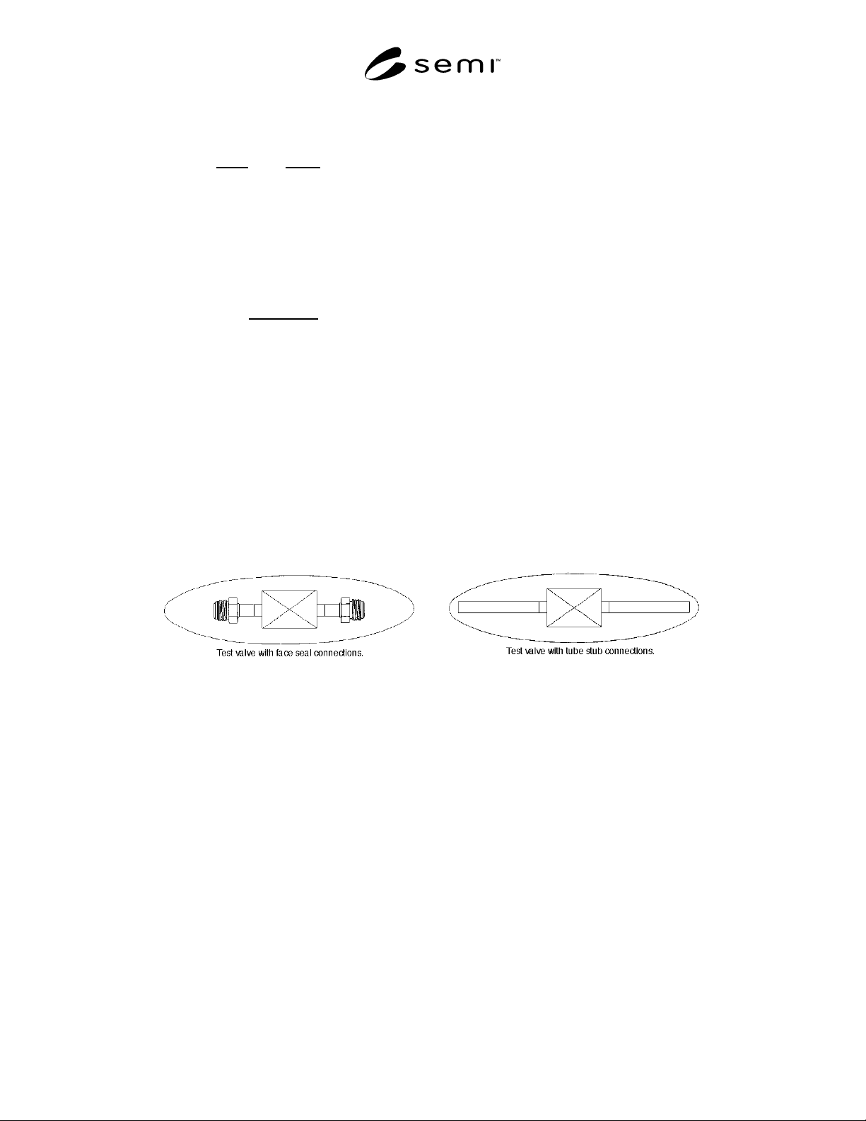
7.1.1 The test valve can be any high purity valve, or a
combination of valve with tube connections, fittings
connection, or expanders which are normally attached
as part of the valve assembly as purchased. It is
important to note that the definition of the “test valve”
is inclusive of all connections and fittings, as supplied
by the manufacturer. This specifically differs from the
ISA procedure, whereby a method is provided to
differentiate the pressure drop contribution of the
attached fittings. It is recognized that flow coefficients
may vary slightly depending upon the end connection
used. Examples of typical test valves are shown in
Figure 1.
Figure 1
Test Valve with Various Connections
SEMI F32-0998 © SEMI 19983
7.2 Test Section Requirements
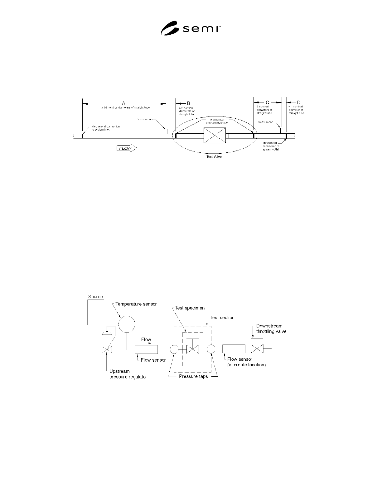
7.2.1 Fixturing of the test valve shall be made in accordance with ANSI/ISA-S75.02, Table 1, where the test valve
is the complete valve assembly including connections, as described above. For reference, ANSI/ISA-S75.02 test
setup is shown in Figure 2.
Figure 2
Fixturing Requirements, Standard Test Section
7.2.2 Tube Connections — Connect ions to the test valve are to be the same as would normally be performed by the
end user as installed. Tube connections are to be full penetration welded by automatic orbital head, with purge gas.
7.2.3 Face Seal Connections — Face seal connectors supplied with the test valve may be either male or female. An
appropriate mating connector shall be welded into the inlet and outlet tubing using full penetration orbital head
welds, and connected to the valve with standard seals.
7.2.4 Compression Fitting Connections — Valves supplied with tube stubs may be connected with compression
fittings.
8 Test Procedure
8.1 Setup — The test setup shall b e as shown in ANSI/ISA-S75.02, Section 3.1. For reference, see Figure 3. The
flowmeter may be upstream or downstream of the test valve, and can also be placed downstream of the throttle valve
when necessary to vent to atmosphere.
Figure 3
Test Setup