semi合集-English.pdf - 第3985页
SEMI F43-0699 © SEMI 1999 5 permanent l y crimp any ferrul es onto the tube stu bs. Nylon ferrules are acceptable. 7.3.2.3 Us ing t he fl ow control device, s e t the test flow to manufactu rer ’s recommended max i mum f…

SEMI F43-0699 © SEMI 1999 4
components used for the construction of the
recommended test apparatus are given because they have
been found to be critical to the proper operation of the
test apparatus as required by the specification.
Deviations from these dimensions have resulted in some
lab facilities not meeting the requirements of the
specification.
7.2.3.2 The spool piece is to be installed when the test
stand is not in use. A continuous low flow (0.1 scfm) is
to be maintained to purge the system. The particle
counter may be turned off. For an extended shutdown,
the system (excluding the CNC) should be pressurized
and capped.
7.2.3.3 After initial construction, the spool piece
should be installed and the test apparatus (except the
CNC) should be pressurized and tested for leaks in the
system. It is recommended that a helium leak detector
or a pressure decay method be used to detect leaks in
the system. The system should then be cleaned by
running a high flow rate of test gas with simultaneous
gentle tapping of all components (except the CNC)
downstream of the final filter F3. This procedure
should be followed by a start-up phase which
characterizes system cleanliness by conducting the
entire test protocol with the control product installed.
This start-up phase should continue and be repeated as
necessary until the counts from the control product have
stabilized at or below the expected number of counts
from the test components.
7.3 Test Procedures
NOTE: Ensure the counter is counting continuously
and reporting data every minute. For the duration of
the test, the counter should be continuously counting,
except where noted in the test protocol.
7.3.1 Background Test
7.3.1.1 Ensure that the spool piece and proper adapters
are in place on the test apparatus.
7.3.1.2 Static Test Close the pneumatic valve
(PV1). Set regulator R1 to 30 psig. Open the
pneumatic valve (PV1) to establish flow. Using the
flow control device, set the test flow to manufacturer’s
recommended maximum flow. Measure the static
background count. Background count is established
when the counter has sampled a minimum of 3 scf, and
the arithmetic average during the last 3 scf of gas
sampled is <2 particles/scf. At a sample flow rate of
0.05 scfm, the time required is one hour. Ensure that
the background counts are stable or decreasing. If
background cannot be achieved after 6 scf have been
sampled, there may be a problem with the counter or
test apparatus.
7.3.1.3 Dynamic Test Set the actuator pressure of
PV1 to its minimum pressure recommended by the
manufacturer to fully open the valve. Actuate the
pneumatic valve PV1 at 30 cycles per minute to
measure the background counts under dynamic test
conditions. Dynamic background count is established
when the counter has sampled a minimum of 3 scf, and
the arithmetic average during the last 3 scf of gas
sampled is < 3 particles/scf. (Estimated dynamic
background count will be verified and altered if
necessary during the validation phase of this test
method.) At a sample flow rate of 0.05 scfm, the time
required is 1 hour. If dynamic background cannot be
achieved after 6 scf have been sampled, there may be a
problem with the counter or test apparatus.
7.3.1.4 Stop the pneumatic valve cycling. Flush the
system for 10 minutes under static test conditions.
7.3.1.5 Purifier Impact Test Impact the spool piece
once per minute for ten minutes with the mechanical
shock device (See Figure 2). The impact background
count should be <4 particles/scf over the ten minutes of
the test. (Estimated impact background count will be
verified and altered if necessary during the validation
phase of this test method.) If impact background
cannot be achieved, repeat the shock a second time. If
the impact background count specification still cannot
be met, there may be a problem with the counter or test
apparatus.
7.3.1.6 Flush the system for 30 minutes at the test flow
rate. Record the resulting count.
7.3.1.7 Turn the CNC pump off while leaving the
CNC power on.
7.3.2 Purifier Static Test
7.3.2.1 Using the flow control device, decrease the
flow rate to 0.1–0.2 scfm, so that some flow remains in
the system while the test purifier is installed.
7.3.2.2 Remove the spool piece by first disconnecting
the downstream fitting and then the upstream fitting.
Immediately install the test component in a fully open
position by first connecting the upstream fitting and
then the downstream fitting. Removal of the spool
piece and installation of the test component to minimize
reactions of the purifier with room air and extraneous
contamination and prevent the counter from cooling off
should take no longer than 3 minutes. Extreme care
should be taken to minimize contamination of the test
apparatus during this operation. The test component is
to be removed from its inner bag in the Class 100 test
area. If the test component has mechanical fittings,
these fittings are to be properly connected. If the test
component has tube ends, the component is to be
installed with clean compression fittings. Do not

SEMI F43-0699 © SEMI 19995
permanently crimp any ferrules onto the tube stubs.
Nylon ferrules are acceptable.
7.3.2.3 Using the flow control device, set the test flow
to manufacturer’s recommended maximum flow.
7.3.2.4 Turn on the counter pump and conduct the
static test. The purifier is to be tested with the valve
PV1 in the fully open position until 85 standard liters (3
scf) of gas have been sampled. Cumulative data should
be recorded at one-minute intervals.
7.3.3 Purifier Dynamic Test
7.3.3.1 This test is to immediately follow the static
test. To conduct the dynamic test, set the actuator
pressure of the actuator attached to valve PV1 to its
minimum actuator pressure as recommended by the
manufacturer to fully open the valve. Actuate valve
PV1 at the rate of 30 cycles/minute for 60 minutes. A
cycle consists of off and on actuation of the valve. The
off and on cycles should be of equal duration.
7.3.4 Purifier Impact Test
7.3.4.1 This test is to immediately follow the dynamic
test. Maintain the test flow rate for 10 minutes, with
the valve PV1 in the fully open position. Impact the
purifier once a minute for 10 minutes, using the
mechanical shock device. Purge the test component by
maintaining the test flow rate for 30 minutes.
7.3.5 Turn the counter pump off and then decrease the
test gas flow rate to ~ 5 slpm.
7.3.6 Remove the test purifier by first disconnecting
the downstream fitting and then the upstream fitting,
and immediately install the spool piece by connecting
the upstream fitting followed by the downstream fitting.
The removed purifier should be immediately valved off
or capped to prevent its exposure to room air.
7.4 Data Presentation
7.4.1 The following test conditions are to be reported
in the data presentation:
• Date and time of test
• Operator
• Test flow rate (scfm)
• Test pressure (psig)
• Test temperature (°C)
• Purifier type, manufacturer, serial number, lot
number, and model number
• CNC manufacturer, serial number, sample flow
rate (scfm), model number, and calibration date
• Test gas type and dew point (°C)
• A schematic of the test apparatus, including
manufacturer's and model numbers of all test
apparatus components
• Calibration dates for the flow meters and the test
date
7.4.2 Graph the static, dynamic and impact portions
of the test separately as counts/minute (measured by the
counter) versus time, including the appropriate
background (measured with the spool piece in place)
with each. Also graph the entire data set as counts per
minute versus time. If different filters are to be
compared, graph their entire data sets together.
7.4.3 Present the entire raw data set in tabular form.
8 Related Documents
8.1 The appropriate particle counter manufacturer's
operating and maintenance manuals should be consulted
when using this test method.
8.2 On particle counter efficiencies: Agarwal, J. K.
and Sem, G. J. "Continuous Flow, Single Particle
Counting Condensation Nucleus Counter." Journal of
Aerosol Science, v.11.4. July 1980:343–357.
8.3 On flow calculations: D. E. Dickie, ed. Crane
Handbook. Construction Safety Association of Toronto.
Ontario, Canada. 1975.
8.4 Statistical reference: Van Slooten, R. A.,
"Statistical Treatment of Particle Counts in Clean
Gases. " Microcontamination, v.4.2. Feb. 1986:32–38.
8.5 Hinds, W. C. Aerosol Technol ogy: Properties,
Behavior, and Measurement of Airborne Particles. John
Wiley & Sons. 1982:187–194.
8.6 Fissan, H. and Schwientek. "Sampling and
Transport of Aerosols." TSI Journal of Particle
Instrumentation, v.2.2. July–December 1987:3–10.
8.7 SEMI F1-96, Specification for Leak Integrity of
High Purity Gas Piping Systems and Components.
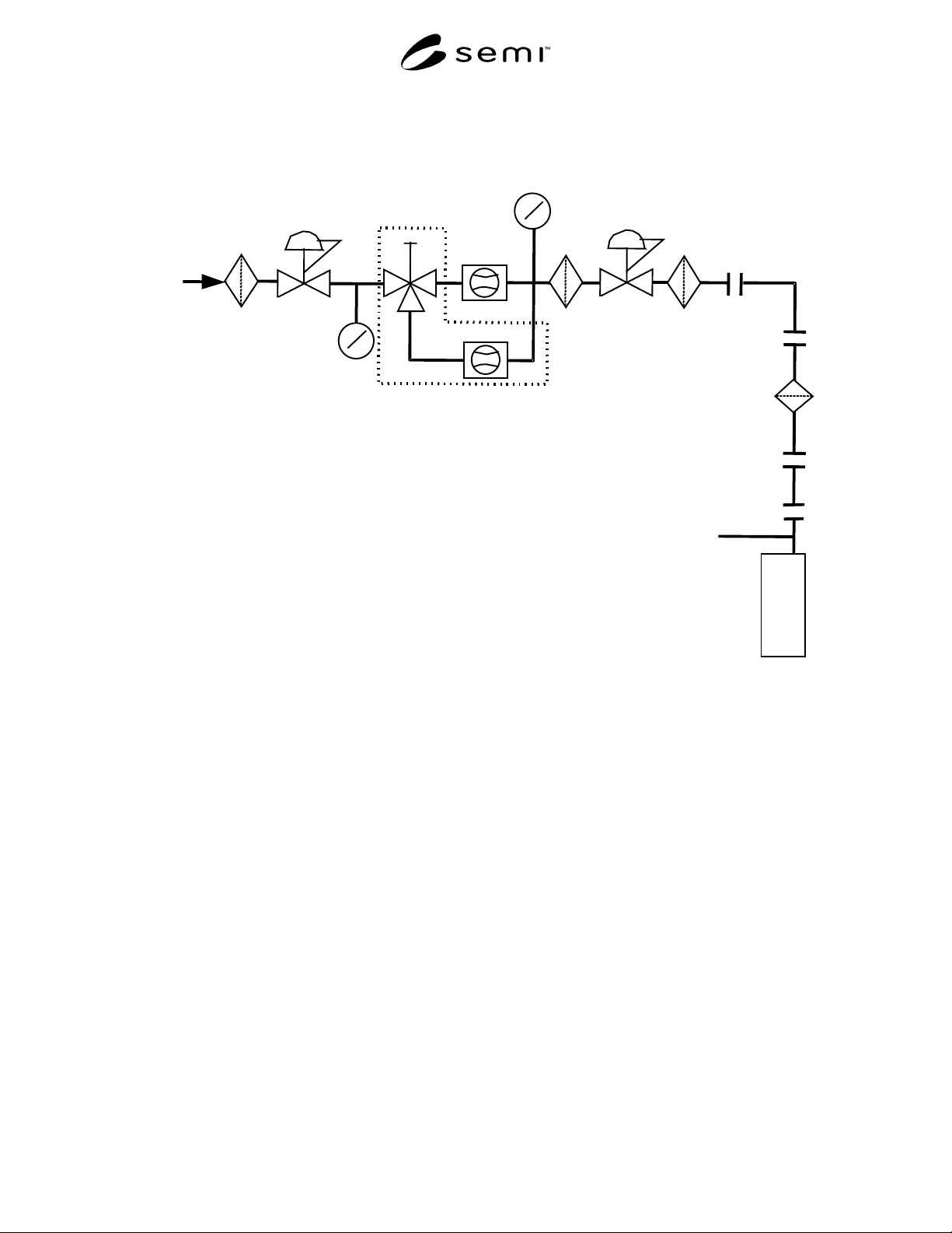
SEMI F43-0699 © SEMI 1999 6
C
N
C
Gas
Inlet
F1
R1
P1
V1
FM1
FM2
F2
PV1
F3
Test
Purifier
Exhaust
P2
F1 = 10" PTFE Membrane Filter
R1 = @ 0-100 psig Outlet Regulator
P1, P2 = Electronics Grade Pressure Gauge (30"-0-60)
V1 = Three-Way Valve
FM1 = Low Flow (0-2 scfm) Flowmeter
FM2 = High Flow (0-20 scfm) Flowmeter
F2, F3 = Electronics Grade Filter
PV1 = Electronics Grade Pneumatic Valve
Figure 1
Schematic of Particle Test Loop