semi合集-English.pdf - 第6542页
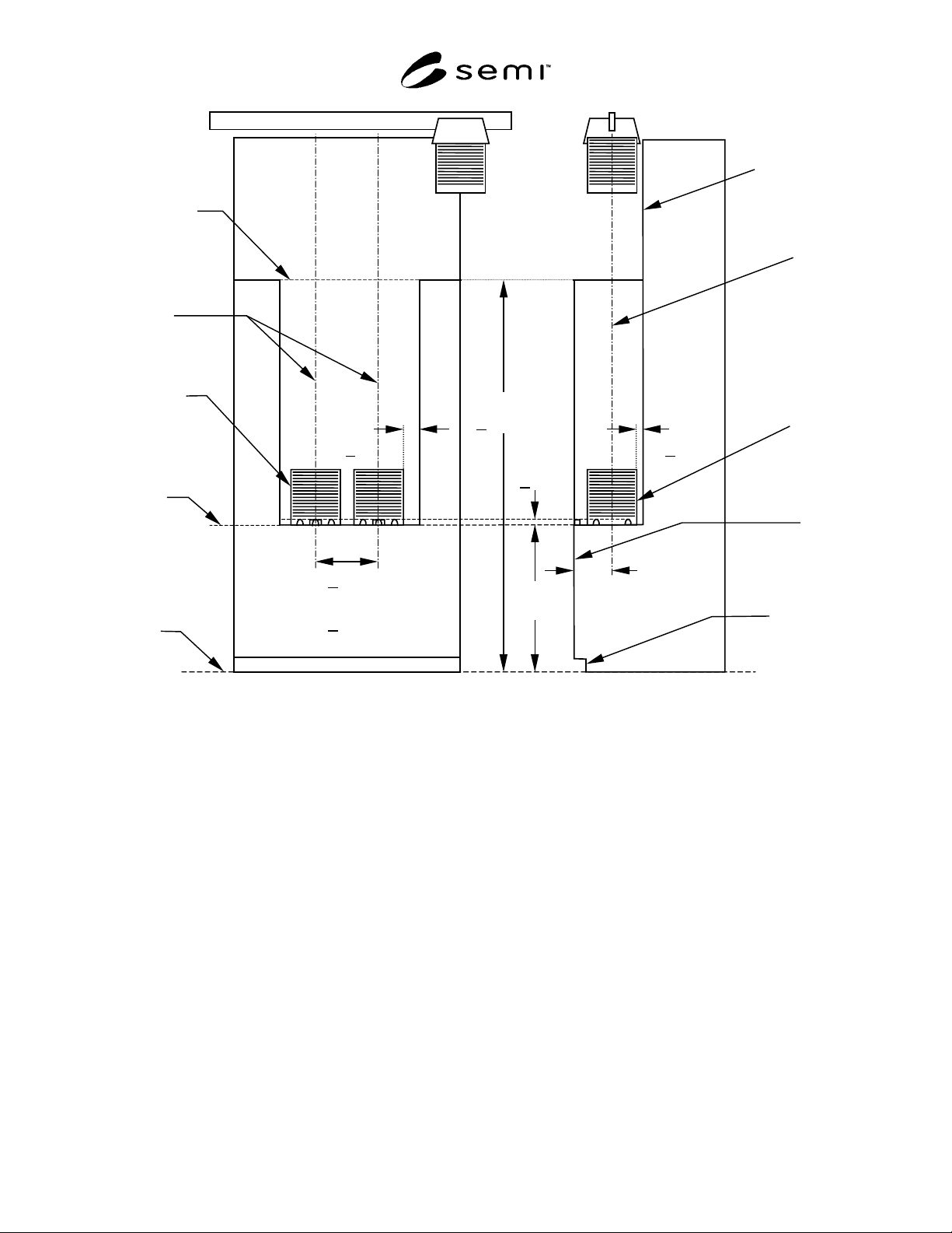
SEMI G82-0301 E © SEMI 2001 4 (frame cassette with handles) equipment boundar y facial datum plane frame casstte front load fac e plane docking interf ace (see SEMI E64) bilateral datum planes frame cassette horizontal d…
SEMI G82-0301
E
© SEMI 2001 3
Table 1 Dimensional Requirements for 300 mm Load Port
Dimension Application Value, mm (in.) Notes
C1 minimum 75 (3.0)
C2 minimum 30 (1.2)
D range
250
0
10
+
−
(9.8
0
4.0
+
−
)
D0 minimum 110 (4.33)
H nominal 900 (35.4) 1
H0 minimum 15 (0.59)
H1 maximum 25 (1.0)
H2 maximum 2600 (102.4 )
HC3 range
32
0.2
0
+
−
(1.26
1.0
0
+
−
)
2
482 (19.0) 3
S minimum
555 (21.9) 4
W1 maximum 130 (5.12)
W2 minimum 205 (8.07)
NOTE 1: This value is ergonomically compatible with the proposed 13 frame cassette and may not be ergonomically compatible with the
proposed 25 frame cassette. The proposed 25 frame cassette may require assisted loading. H to be fully adjustable at installation over the range of
890 to 910 mm (35 to 35.8 inches).
NOTE 2: To avoid confusion, HC3 is used instead of H3 because H3 stands for another dimension in SEMI E15.1.
NOTE 3: Frame cassette (see SEMI G77) without manual side handles
NOTE 4: Frame cassette (see SEMI G77) with manual side handles
9 Table 1 Dimensions Definition
9.1 See SEMI E15 for definitions of the following terms used in this specification:
9.1.1 C1
9.1.2 C2
9.1.3 H
9.1.4 H1
9.1.5 S
9.2 D — allowable load depth to frame cassette centroid.
9.3 D0 — minimum rear clearance of equipment boundary below H1 from facial datum plane.
9.4 H0 — minimum height from the bottom of equipment boundary below H1 to horizontal datum plane.
9.5 H2 — maximum overhead track clearance from the floor.
9.6 HC3 — allowable height of conveyor rail from horizontal datum plane.
9.7 W1 — maximum side clearance of equipment boundary below H1 from bilateral datum plane.
9.8 W2 — minimum side clearance of equipment boundary below H1 from bilateral datum plane.
SEMI G82-0301
E
© SEMI 2001 4
(frame cassette with handles)
equipment
boundar
y
facial
datum
plane
frame
casstte
front
load
face
plane
docking
interface
(see
SEMI E64)
bilateral
datum
planes
frame
cassette
horizontal
datum
plane
floor
H
= 900
H1
< 25
D = 250
C2
> 30
> 482
(frame cassette without handles)
> 555
C1
> 75
+0
–
10
S
H2
< 2600
overhead
track
clearance
Figure 1
Load Port Requirements
SEMI G82-0301
E
© SEMI 2001 5
bilateral
datum plane
horizontal
datum plane
H0 > 15
example of conveyor
rail application
conveyor rail is lowered
below fork lift exclusion zone
W1 < 130
W2 > 205
equipment boundary
above H1
frame cassette
C1 > 75
C1 > 75
W1 < 130
W2 > 205
equipment boundary
bilateral
datum plane
facial datum plane
load face plane
D0 > 110
equipment boundary
above H1
equipment boundary
below H1
C2 > 30
H1 < 25
Top
Front
HC3 =32
+2
−
0
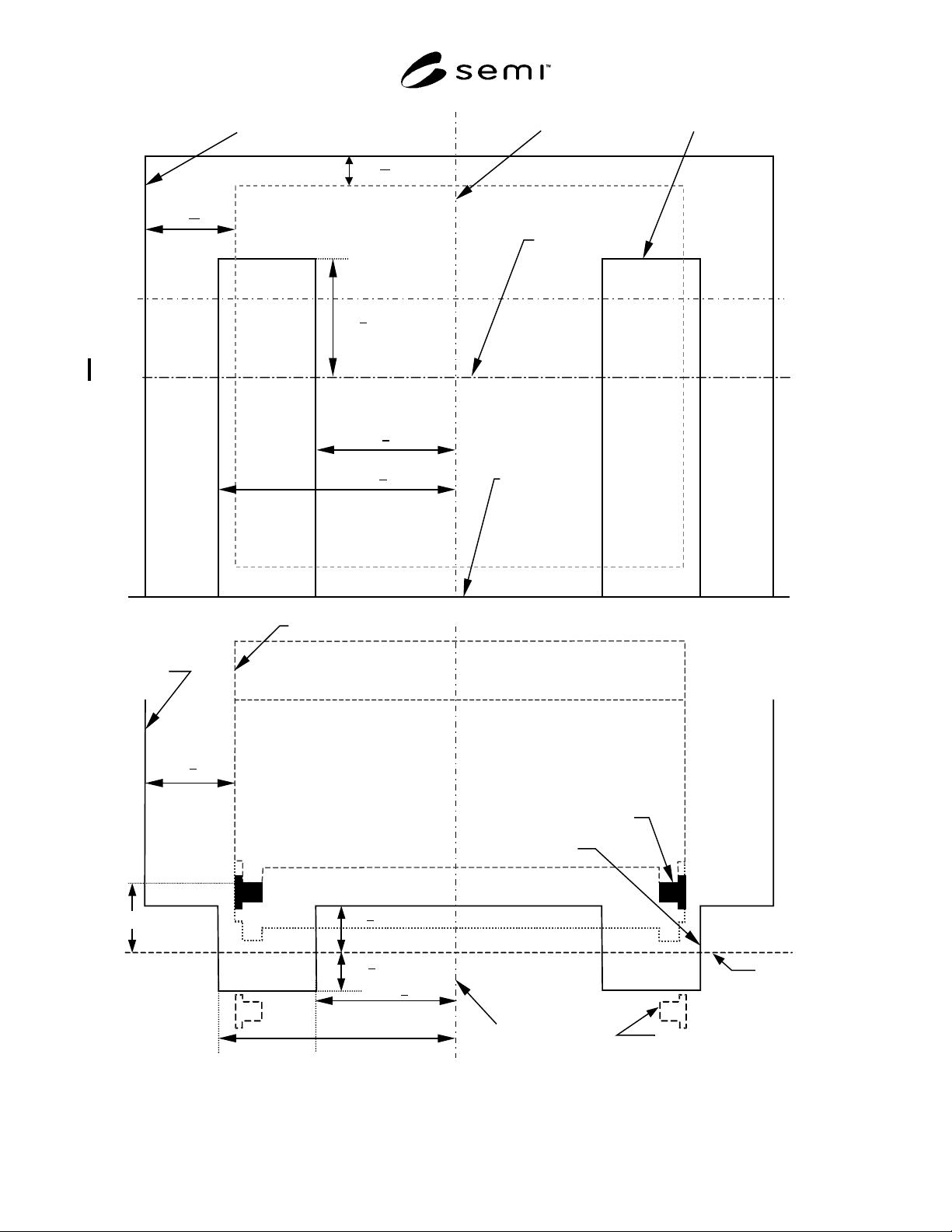
Figure 2
Trenches and Conveyor Rails