semi合集-English.pdf - 第3942页
Table 4 MFC and MFM Interface Re commendations Option 1 MFC and MFM Option 2 MFC and MFM End-to-End Lengths: 1/4-inch Integral/fixed male face seal 1/4-inch Swivel face seal (male o r female) 1/4-inch Tube weld 124 mm (4…
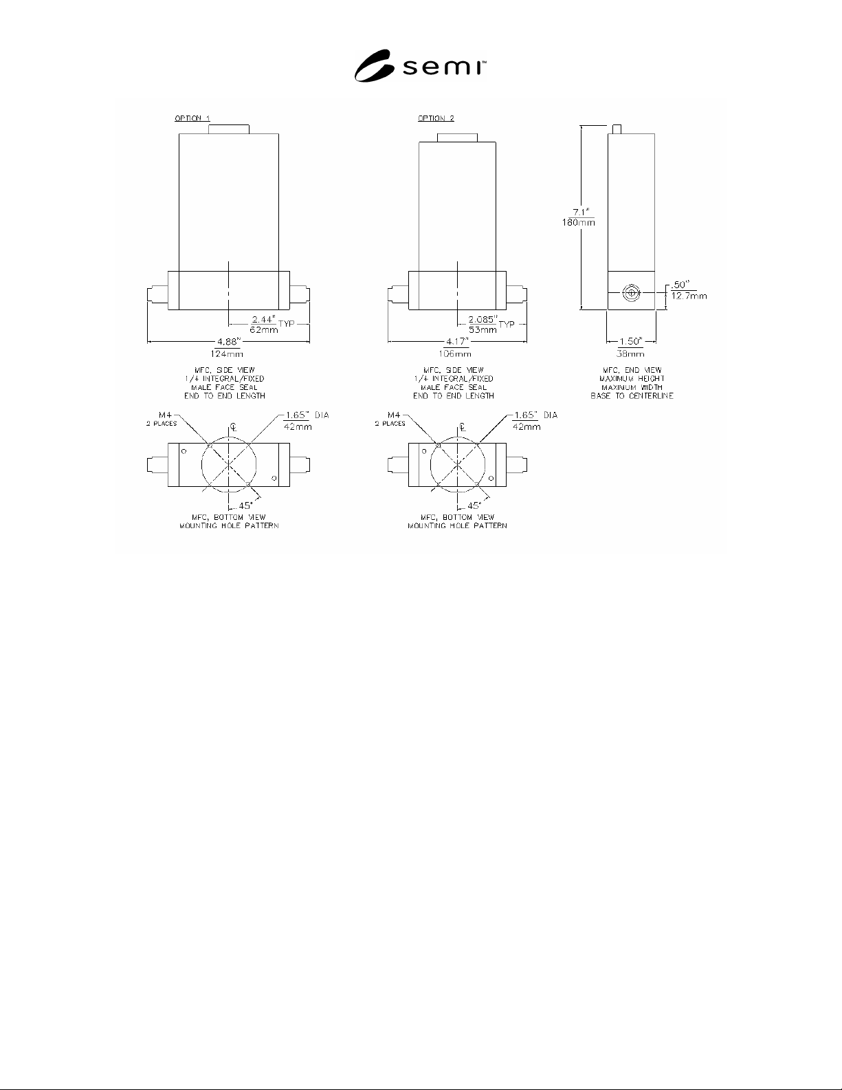
Figure 4
MFC and MFM Interface Design
SEMI F36-0299 © SEMI 1999, 2004 8
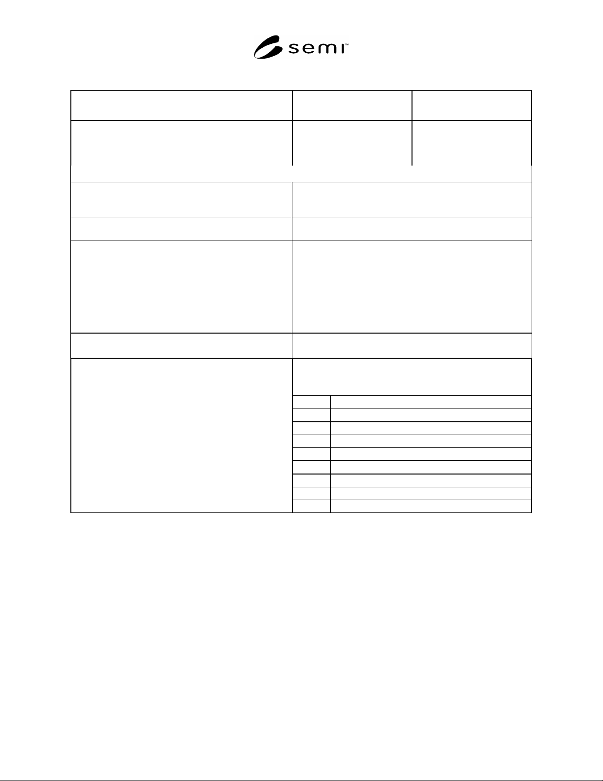
Table 4 MFC and MFM Interface Recommendations
Option 1
MFC and MFM
Option 2
MFC and MFM
End-to-End Lengths:
1/4-inch Integral/fixed male face seal
1/4-inch Swivel face seal (male or female)
1/4-inch Tube weld
124 mm (4.88 in.)
-
-
106 mm (4.17 in.)
-
-
NOTE 1: The tolerance on length is ± 0.50 mm (0.020 in.) from the component centerline to each end.
Overall Component Envelope:
Maximum height
Maximum width
180 mm (7.1 in.)
38 mm (1.5 in.)
Base to Centerline of Flow Path:
12.7 mm (0.50 in.)
± 0.3 mm (0.012 in.)
Mounting provisions:
Threaded holes
Pattern
M4 0.7 6H; 3 mm (0.12 in.) minimum perfect thread depth
42 mm (1.65 in.) bolt circle centered on bottom of base with two
threaded holes 180° apart and 45° off of the vertical or horizontal
axis.
One hole in each of the upper left and lower right quadrants when
looking at the bottom of the component.
Fittings:
Process
1/4-inch
Electrical
9-pin sub-D connector
Analog signal pin out as follows:
Pin 1. Valve Closed (Ground Pin to Close Valve)
Pin 2.
05 V
DC
Flow Signal Output
Pin 3. +15 V
DC
Power Supply
Pin 4. Power Common
Pin 5. -15 V
DC
Power Supply
Pin 6.
05 V
DC
Setpoint Input
Pin 7. Output Common
Pin 8. Setpoint Common
Control:
Pin 9. Valve Test Point
SEMI F36-0299 © SEMI 1999, 2004 9
11 Pressure Transducers
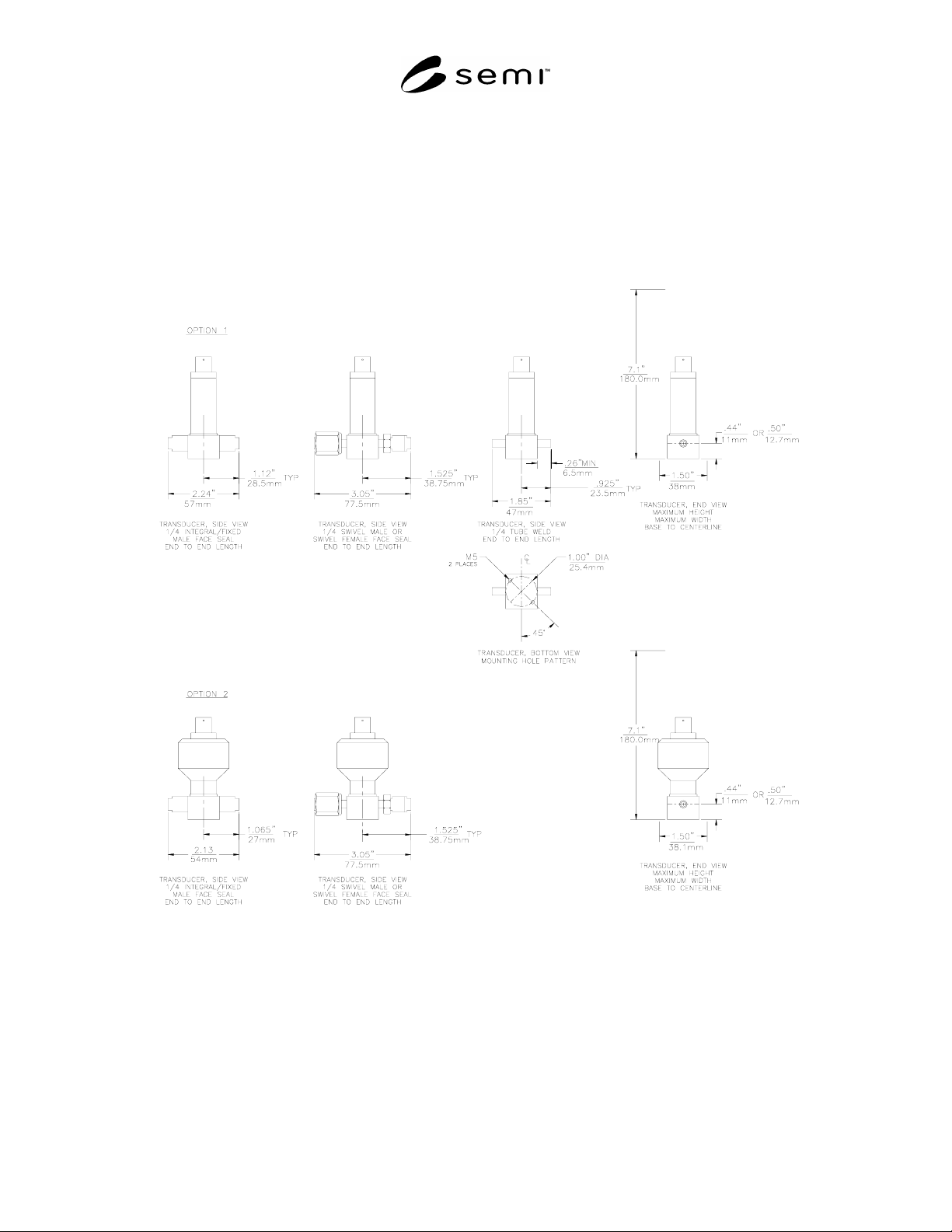
11.1 Pressure transducers should conform to the interface design recommendations appearing in Figure 5 and Table
5.
11.2 To improve modularity of gas distribution systems the following recommendation should be considered for
future pressure transducer design. This recommendation would match the pressure transducer interface design to the
dimensions of both the shut-off valve Option 1 found in Table 2 and pressure regulator Option 1 found in Table 3.
Figure 5
Pressure Transducer Interface Design
SEMI F36-0299 © SEMI 1999, 2004 10