semi合集-English.pdf - 第6345页
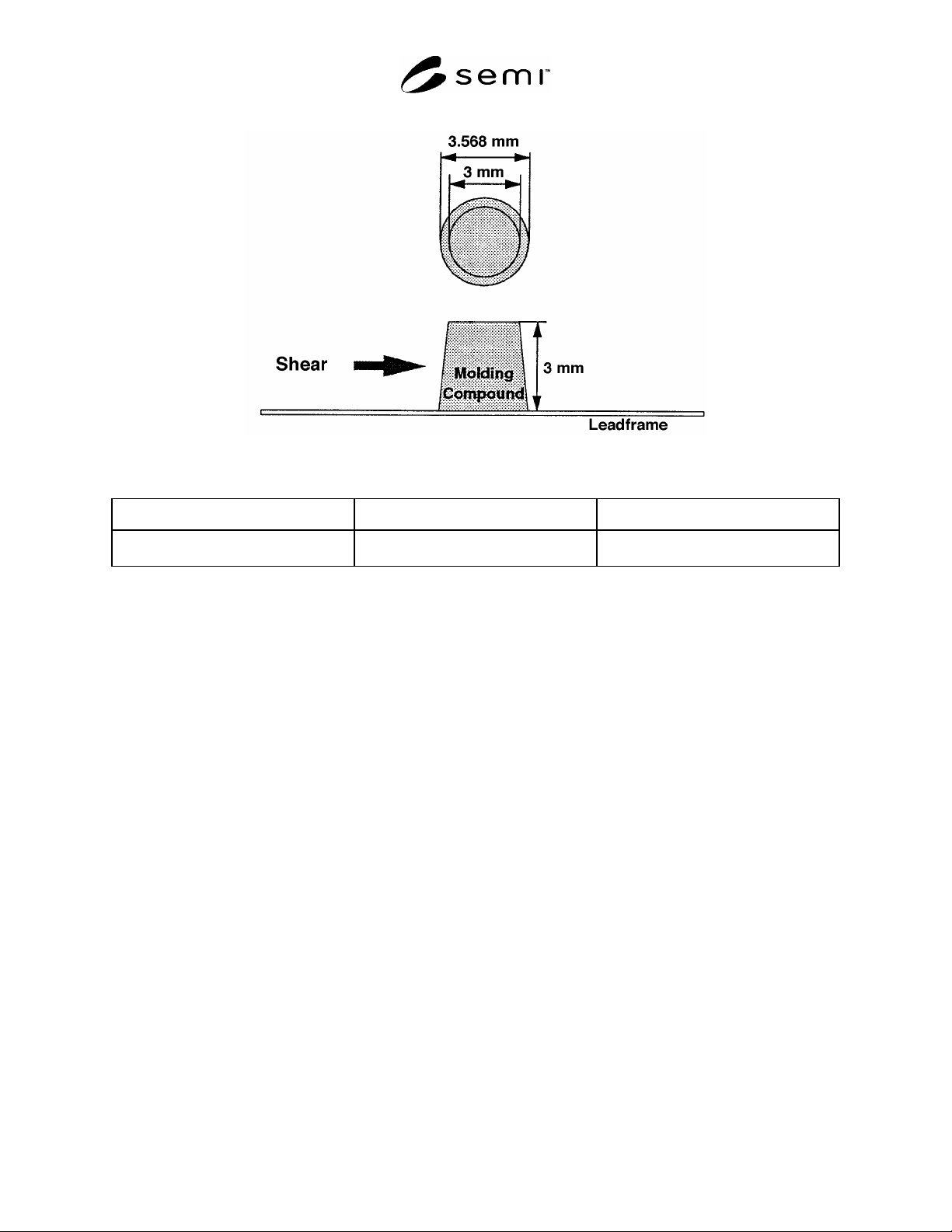
SEMI G69-0996 © SEMI 1996, 2004 2 Figure 1 Sample for Shear Method Adhesive Area Leadframe Thickn ess Height of Molding Compound 10 ± 0.5 mm 2 0.254–0.125 mm (0.15 mm is recommended) 3 ± 0.15 mm

1 SEMI G69-0996 © SEMI 1996, 2004
SEMI G69-0996 (Reapproved 1104)
TEST METHOD FOR MEASUREMENT OF ADHESIVE STRENGTH
BETWEEN LEADFRAMES AND MOLDING COMPOUNDS
This test method was technically approved by the Global Assembly & Packaging Committee and is the direct
responsibility of the Japanese Packaging Committee. Current edition approved by the Japanese Regional
Standards Committee on July 23, 2004. Initially available at www.semi.org September 2004; to be published
November 2004. Originally published in 1996.
1 Purpose
1.1 This document describes procedures for measuring
adhesive strength between leadframes and molding
compounds for semiconductor packages.
1.2 The procedures include shear test, pull test, and
three-point bending techniques.
2 Scope
2.1 This document may be used on all types of
semiconductor leadframe and molding compound.
2.2 The methods help leadframe manufacturers,
molding compound manufacturers and their customers
in evaluating leadframes, and molding compounds as a
guideline.
2.3 The methods in this document use SI units.
NOTICE: This standard does not purport to address
safety issues, if any, associated with its use. It is the
responsibility of the users of this standard to establish
appropriate safety and health practices and determine
the applicability of regulatory or other limitations prior
to use.
3 Terminology
3.1 None.
4 Summary of Method
4.1 Shear Method — A frustum-shaped button of
molding compound on the surface of a leadframe
sample is sheared off the leadframe surface using a
tensile tester (see Figure 1).
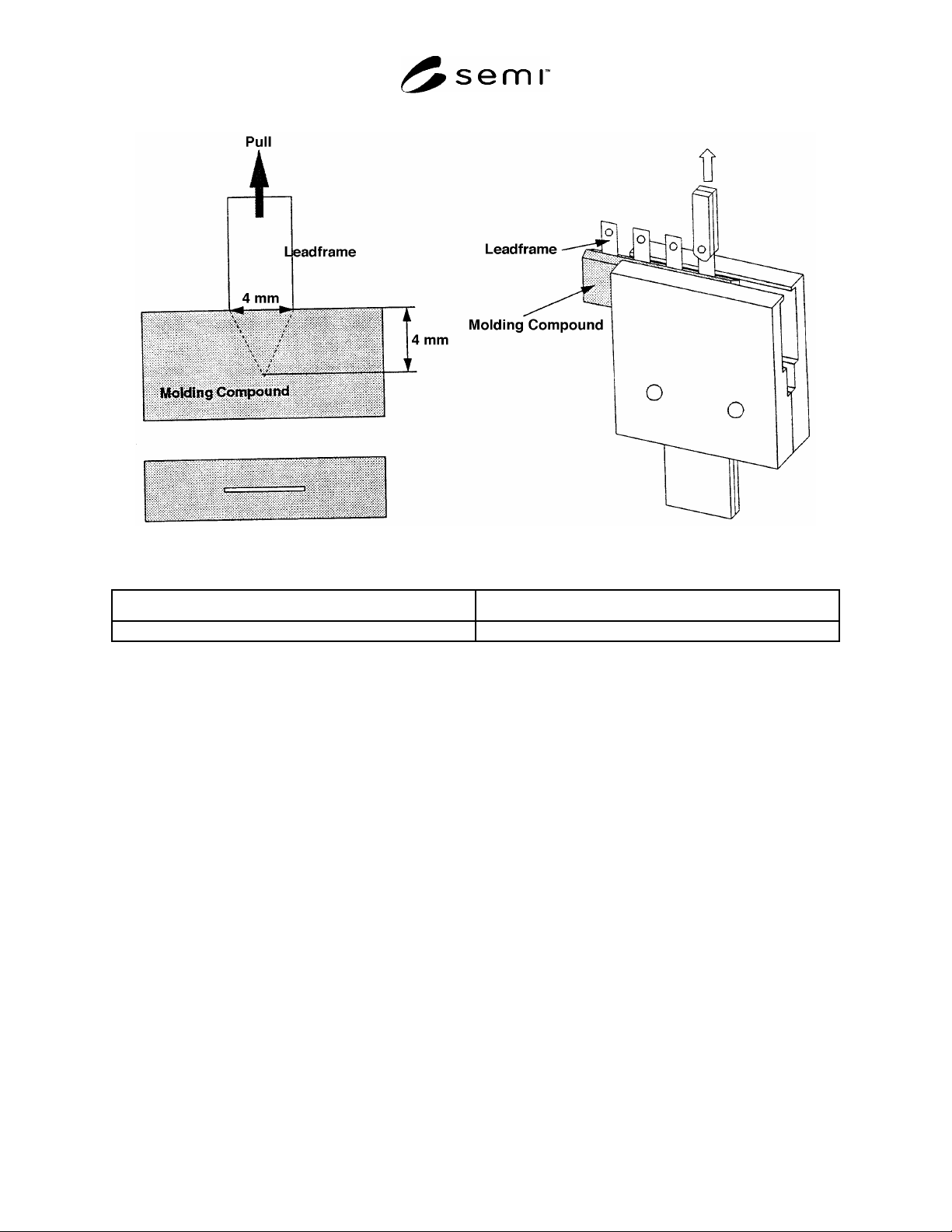
4.2 Pull Method — A sample of leadframe material
molded into the side of a block of a molding compound
is pulled out using a tensile tester (see Figure 2).
4.3 Three-Point Bending Method
1
— Molding
compound is molded onto the surface of a leadframe
sample such that part of the leadframe is free of
1 A. Nishimura, I. Hirose and N. Tanaka, “A New Method for
Measuring Adhesion Strength of IC Molding Compounds”, ASME
Journal of Electronic Packaging, Vol. 114, pp 407-412, 1992
molding compound adherence to the surface. Using a
bending technique, the adherent molding compound is
cracked away from the surface. This process is repeated
from both sides of the sample in order to calculate the
true adhesive strength (see Figure 3).
5 Equipment
5.1 Tensile Tester
5.1.1 Measurement Range — Maximum 980 N (100
kgf)
5.1.2 Accuracy — ± 1%
5.1.3 Crosshead Speed — 2–10 mm/min
(recommended), constant speed.
5.1.4 Fixtures suitable for holding the samples,
shearing the molding compound, pulling the leadframe,
and applying bending load.
5.2 Chart Recorder
5.3 Transfer molding machine or suitable replacement
that can encapsulate individual samples with required
pressure and temperature.
5.4 Pre-Heater — High frequency heater for molding
compounds.
5.5 Molds — Suitable to mold the samples as shown in
Figures 1, 2, and 3.
5.6 Recirculating Air Oven — With controller in range
of 170–180°C.
5.7 Equipment to pre-treat the leadframe sample, as
required.
5.8 Ultrasonic inspection apparatus for three-point
bending method.
6 Configuration and Dimension of Sample
6.1 The sample configuration and dimensions for
measurement are shown in Figures 1, 2, and 3.
SEMI G69-0996 © SEMI 1996, 2004 2
Figure 1
Sample for Shear Method
Adhesive Area Leadframe Thickness Height of Molding Compound
10 ± 0.5 mm
2
0.254–0.125 mm
(0.15 mm is recommended)
3 ± 0.15 mm
3 SEMI G69-0996 © SEMI 1996, 2004
Figure 2
Sample for Pull Method
Adhesive Area Molding Compound Sample Thickness
16 ± 0.8 mm
2
(both sides) 3.5–4.0 mm (equivalent to DIP 16 300 mil)