semi合集-English.pdf - 第6131页
SEMI G28-0997 © SE MI 1986, 1997 3 10 Packaging, Marking, and P a c k ing List 10.1 Packagi ng — The sh ipping co n t ai ners and materials shall be suitably designed to p rovide the leadframes with protection ag ai nst …

SEMI G28-0997 © SEMI 1986, 1997 2
NOTE: Maximum coin depth may also be constrained by
minimum lead spacing requirement given in Section 7.1.3.1.
Minimum coin depth may also be constrained by minimum
bond area requirement given in Section 7.1.1.
7.1.3 X-Y Plane Lead Spacing and Location
7.1.3.1 Spacing between leads to be 0.004" (0.100
mm) minimum.
7.1.3.2 Leads to be located so that a 0.007" diameter
circle centered on the nominal center of the coined lead
in width and 0.006" (0.152 mm) back from lead tip in
length shall be totally encompassed by the coined area.
7.1.4 X-Y Plane Die Attach Pad Location — Die
attach pad to be located within ± 0.002" (0.051 mm) as
measured from the centerline of the reference hole in
the side rail.
7.1.5 Lead Twist — Shall not exceed 3°30’ or 0.0006"
(0.015 mm) per 0.010" (0.254 mm) of lead width.
7.1.6 Die Attach Pad Tilt and Flatness
7.1.6.1 Tilt — 0.001" (0.025 mm) maximum per
0.100" (2.54 mm) in the undepressed state. 0.002"
(0.015 mm) maximum per 0.100" (2.54 mm) in the
depressed condition.
7.1.6.2 Flatness — To be within 0.002" (0.051 mm)
T.I.R. per 0.100" (2.54 mm) when measured from the
center to each of the four corners. The corners are
defined at 0.005" (0.127 mm) from each edge.
7.1.7 Die Attach Pad Downset — ± 0.002" (0.051
mm) as measured from the center of the pad to a point
on the bar pad support strip. The nominal downset
recommended is 0.012" (0.30 mm) for 0.010" (0.25
mm) thick material and 0.008" (0.20 mm) for 0.008"
(0.20 mm) thick material.
7.1.8 Lead and Die Attach Pad Coplanarity
7.1.8.1 The coplanarity relationship is based on
reference to the Z plane (see SEMI G10).
7.1.8.2 Lead Planarity — The lead tips as measured in
the center of the back, uncoined surface of the lead tip
shall be located within the following tolerances of the Z
plane:
Lead Planarity: ± 0.004"
7.1.8.3 Die Attach Pad Planarity — The die attach
pad when measured at the center must be within the
following tolerances of the Z plane:
Pad Planarity: + 0.003"/-0.005"
7.2 External Area and Strip
7.2.1 Material
7.2.1.1 0.008" (0.20 mm) material thickness
recommended for 0.150" wide packages.
7.2.1.2 0.010" (0.25 mm) material thickness
recommended for 0.300" wide packages.
7.2.1.3 Nominal Thickness — Tolerances shall be ±
0.0003" (0.008 mm).
7.2.1.4 Width Tolerance — ± 0.002" (0.051 mm).
7.2.2 Coil Set — Maximum of 0.125" (3.175 mm)
measured in a free standing state over strip length.
7.2.3 Crossbow — Crossbow shall not exceed the
following dimensions:
Maximum Crossbow: ± 0.005" (0.127 mm)
7.2.4 Camber — Shall not exceed 0.002" (0.05 mm)
over a gage length of 6.00" (150 mm). (See SEMI
G10.)
7.2.5 Progression — Should be specified along with
tolerances on the drawing.
7.2.6 Burrs — Burrs shall be firmly attached and able
to withstand a probe force of 10 grams. Vertical burrs
inside the dambar shall not exceed 0.001" (0.02 mm).
Vertical burrs outside the dambar and horizontal burrs
in any location shall not exceed 0.002" (0.05 mm).
7.2.7 Pits and Slugmarks
7.2.7.1 Within functional area and on external leads
there shall be no slugmarks. Pits shall not exceed
0.0003" (0.008 mm) in depth and 0.0005" (0.013 mm)
in largest surface dimension in these areas.
7.2.7.2 Areas Other than 7.2.7.1 — Pits and
imperfections shall not affect leadframe strength
regardless of size and shall not exceed 0.002" (0.05
mm) in depth and 0.005" (0.127 mm) in largest surface
dimension.
7.2.8 Strip Length Cutoff — (See SEMI G10.)
7.2.8.1 Strip cutoff location and tolerance shall be
detailed on the drawing.
7.2.8.2 Overall strip length and tolerance shall be
detailed on the drawing.
8 Functional Testing
Functional testing shall be agreed upon between vendor
and customer.
9 Sampling
Sampling based on ANSI/ASQC Z1.4 shall be agreed
between supplier and purchaser.

SEMI G28-0997 © SEMI 1986, 19973
10 Packaging, Marking, and Packing List
10.1 Packaging — The shipping containers and
materials shall be suitably designed to provide the
leadframes with protection against normal
transportation damage risks which include crushing and
spillage, and exposure to moisture and other corrosive
gases.
10.1.1 The inner packaging materials for cut strips
must not cause particulate contamination on the
leadframes and shall be clean room compatible as
defined by the customer. The leadframes boxes shall be
vacuum sealed in a bag with a desiccant. If the
leadframes are to be delivered in coil form, the coil
diameter shall be set in the purchase order (see SEMI
G9).
10.2 Marking
10.2.1 Internal Packages — Each internal package
shall be clearly marked with the following information,
as appropriate:
a. Customer’s part number
b. Customer’s purchase order number
c. Drawing number (customer’s and/or vendor’s, as
requested by customer)
d. Vendor’s shipping lot number
e. Quantity
f. Date of Manufacture
g. Any agreed upon certification data
10.2.2 External Packages — The packing list on the
outside of the external package shall contain the
following information:
a. Customer’s part number
b. Customer’s purchase order number
c. Quantity
d. Shipping Date
e. Any specific instructions for receiving dock
personnel
11 Certification
11.1 Upon request of the customer in the contract or
purchase order, a vendor’s certification that the product
was manufactured and tested in accordance with this
specification, together with a report of the test results
shall be furnished at the time of shipment. However, if
the customer does perform inspection and test on a
certified shipment and the product fails to meet the
requirements, the product shall be subject to rejection.
11.2 If the customer and vendor agree, the product
may be certified as capable of meeting this
specification. In this context, capable of meeting
signifies that the vendor is not required to perform all
the inspections and tests. However, if the customer does
perform inspection and test on a certified shipment and
the product fails to meet the requirements, the product
shall be subject to rejection.
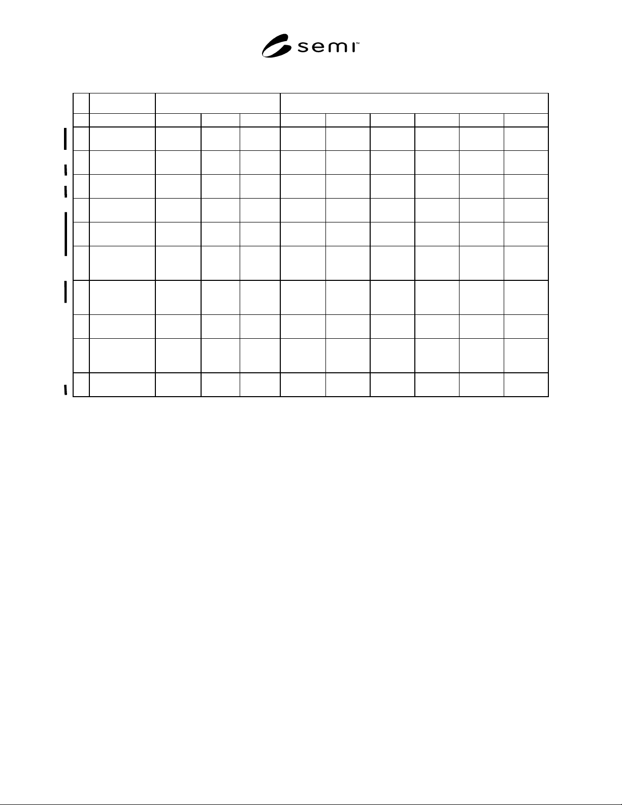
SEMI G28-0997 © SEMI 1986, 1997 4
Table 1
0.150 WIDE 0.30 WIDE (J-COMPATIBLE)
81416141618202428
MATERIAL
GAGE
0.008"
(0.200 mm)
0.008
(0.200)
0.008
(0.200)
0.010
(0.250)
0.010
(0.250)
0.010
(0.250)
0.010
(0.250)
0.010
(0.250)
0.010
(0.250)
A STRIP WIDTH 0.600
(15.2)
0.600
(15.2)
0.600
(15.2)
0.720
(18.30)
0.720
(18.30)
0.720
(18.30)
0.970
(24.60)
0.970
(24.60)
0.970
(24.60)
B PROGRESSION 0.336
(8.53)
0.336
(8.53)
0.336
(8.53)
0.674
(17.12)
0.674
(17.12)
0.674
(17.12)
0.674
(17.12)
0.674
(17.12)
0.674
(17.12)
CTOOLING
HOLE
0.060
(1.52)
0.060
(1.52)
0.060
(1.52)
0.060
(1.52)
0.060
(1.52)
0.060
(1.52)
DDAMBAR
WIDTH 0
0.010
(.250)
0.010
(.250)
0.010
(.250)
0.010
(.250)
0.010
(.250)
0.010
(.250)
EDAMBAR
DISTANCE
FROM CL
0.079
(2.00)
0.079
(2.00)
0.079
(2.00)
0.156
(4.00)
0.156
(4.00)
0.156
(4.00)
0.156
(4.00)
0.156
(4.00)
0.156
(4.00)
F LEAD LENGTH
CL TO LEAD
RAIL
0.167
(4.24)
0.167
(4.24)
0.167
(4.24)
0.322
(8.18)
0.322
(8.18)
0.322
(8.18)
0.322
(8.18)
0.322
(8.18)
0.322
(8.18)
GPKG. LENGTH
BOUNDARY
0.098
(2.49)
0.172
(4.37)
0.198
(5.03)
0.181
(4.60)
0.198
(5.03)
0.231
(5.87)
0.255
(6.48)
0.307
(7.80)
0.356
(9.04)
HPARTS PER
STRIP (STRIP
LENGTH)
24
(8.064)
24
(8.064)
24
(8.064)
12
(8.088)
12
(8.088)
12
(8.088)
12
(8.088)
12
(8.088)
12
(8.088)
IPAD
DOWNSET
0.008
(0.200)
0.008
(0.200)
0.008
(0.200)
0.012
(0.305)
0.012
(0.305)
0.012
(0.305)
0.012
(0.305)
0.012
(0.305)
0.012
(0.305)