semi合集-English.pdf - 第6011页
SEMI G1-96 © SEMI 1 980, 199 6 4 9.1.3.2 Die-Attach Sur face (on Base C e ra mic) — 0.005" (0.127 m m) dim e nsion in t he plane of the co m ponent, or greater than 0.001 " (0.254 m m) above the surface of the …

SEMI G1-96 © SEMI 1980, 19963
5.19 void — An absence of metallization or glass from
a designated metallized or glassed area on a ceramic
surface.
6 Ordering Information
Purchase orders for cerdip components or sub-
assemblies furnished to this specification shall include
the following items:
6.1 Current drawing revision detai ling:
6.1.1 All dimensions and tolerances per ANSI
Y14.5M practices
6.1.2 Type and color of ceramic
6.1.3 Type and thickness of glass
6.1.4 Type and thickness of die pad metallization
NOTE 3: If sub-assemblies are purchased, the leadframe
details shall be as described in SEMI G2. In some cases,
unlike the frames described in SEMI G2, the leadframes may
also have a die-attach pad. If required, the external lead
plating requirements for these sub-assemblies shall also be
specified. (See SEMI G20 for general details of lead finishes.)
If sub-assemblies are purchased, leadframe inspection shall
follow the requirements detailed in Section 9.
6.2 Incoming Inspection and Functional Tests — See
Sections 9 and 10.
6.3 Incoming Sampling Procedures — See Section 11.
6.4 Packaging and Marking Requirements — See
Section 12.
6.5 Vendor Certification Requirements — See Section
13.
6.6 Any additions to, or variations from, this
specification.
7 Dimensions
The components or sub-assemblies described in this
specification shall produce packaged devices that
conform to the outline dimensions and lead numbering
for cerdip package constructions detailed in:
— JEDEC Publication 95 and
— MIL-STD-1835.
Package manufacturing tolerances shall be agreed upon
between user and supplier and detailed in the drawings.
Typical dimensions and tolerances for standard bases
and caps are shown in the appendices at the end of this
specification.
8 Materials
The definitions defect criteria and functional tests
described in this specification relate to package
components made with the following materials:
8.1 Bases, Window Frames, and Caps
8.1.1 Material — Ceramic with 90% alumina,
minimum content.
8.1.2 Color — Black, dark brown, or dark violet.
8.2 Sealing Material
8.2.1 Material — Solder glass desig ned to seal metal
(typically Iron-Nickel-Cobalt alloy per MIL-M-38150,
Type A or Iron-Nickel alloy per MIL-M-38150 Type B)
to ceramic.
8.3 Die-Attach Pad
8.3.1 Material — Thick film gold or other specified
material.
8.4 Leadframe
8.4.1 Leadframes, whether purchased as component or
in sub-assemblies, shall conform to the requirements of
SEMI G2 as required.
9 Defect Limits
The following defects shall be cause for rejection if the
limits shown are exceeded:
NOTE 4: The criteria apply to purchased components and
pre-assemblies, as applicable, or, where applicable, to units
assembled by the user to process conditions agreed upon
between the user and supplier.
9.1 Ceramic Components
9.1.1 Cracks — Any crack.
9.1.2 Chips — See Figures 1 and 2.
9.1.2.1 Corner Chips — 0.030" (0.762 mm) × 0.030"
(0.726mm) × 25% of the package element thickness.
9.1.2.2 Edge Chips — 0.100" (2.54 mm) × 0.030"
(0.726mm) × 25% of the package element thickness.
9.1.2.3 Critical Seal Area — Chips shall not reduce
the critical seal path, at any point, more than 30%. No
more than four chips are allowed in this area, regardless
of loss of seal length.
9.1.3 Burrs, Projection (Fins), and Blisters
9.1.3.1 Bases, Caps, and Window Frames — 0.005"
(0.127 mm) maximum allowable dimension in the plane
of the component, or greater than 0.003" (0.076 mm) in
height.
SEMI G1-96 © SEMI 1980, 1996 4
9.1.3.2 Die-Attach Surface (on Base Ceramic) — 0.005" (0.127 mm) dimension in the plane of the component, or
greater than 0.001" (0.254 mm) above the surface of the metallization excluding a zone, 0.010" (0.254 mm) wide,
around the periphery of the cavity.
9.1.4 Camber — Shall be agreed upon between user and supplier and specified on the component or sub-assembly
drawing. Standard limits shall be 0.003"/inch (0.003 mm/mm), maximum, with a minimum allowable camber of
0.002" (0.051 mm).
9.1.5 Foreign Material — 0.020" (0.508 mm) maximum allowable surface dimension or 0.005" (0.127 mm) in
height. No more than three sites allowed and a minimum separation of 0.030" (0.762 mm) between sites.
9.2 Glass Sealant
9.2.1 Chips and Voids — 0.010" (0.025 mm) maximum allowable dimension. In the critical seal, there shall be no
more than four acceptable chips or voids. In critical and non-critical seal areas, there shall be no voids after a glass
flow cycle.
9.2.2 Glass Misalignment — (After glass flow on components, see Figure 3, or on sub-assemblies.)
9.2.2.1 Glass Overhang — 0.015" (0.381 mm) maximum extension from the ceramic edge.
9.2.2.2 Glass Rundown — 50% of the package element thickness.
9.2.2.3 Glass Rundown into the Die-Attach Cavity — 0.010" (0.254 mm) maximum extension from the ceramic
surface into the cavity.
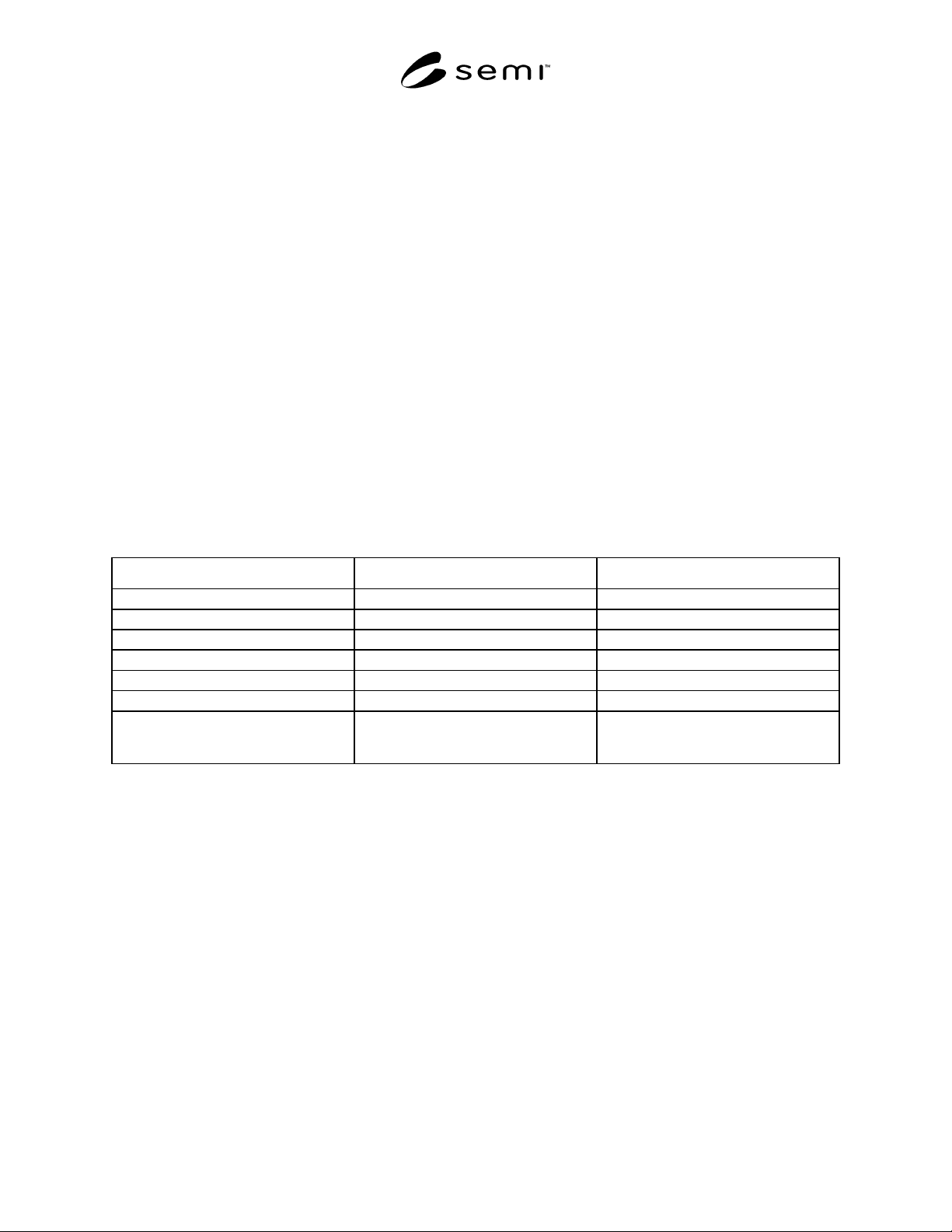
9.2.2.4 Glass Pullback (After Glass Flow) — See Table 1 and Figure 3.
Table 1 Maximum Allowable Pullback
Area of Package Package Row Spacing Package Row Spacing
0.300" (7.500 mm) and 0.400"(10.16 mm) 0.600" (15.24 mm) and larger
Side external (critical seal area) 0.010" (0.254 mm) 0.015" (0.381 mm)
Side external (non-critical seal area) 0.015" (0.381 mm) 0.015" (0.381 mm)
End external 0.020" (0.508 mm) 0.020" (0.508 mm)
Side cavity 0.010" (0.254 mm) 0.015" (0.381 mm)
End cavity 0.010" (0.254 mm) 0.015" (0.381 mm)
Maximum allowable critical seal length
reduction on any one side, as measured
between the cavity and the external side
0.015" (0.381 mm) 0.020" (0.508 mm)
NOTE 5: Regardless of the maximum criteria noted in Table 1, the critical seal length at any point shall not be reduced any more
than 30%.
9.2.2.5 Foreign Material — 0.020" (0.508 mm) maximum allowable surface dimension in the plane of the glass,
but 0.010" (0.254 mm) in the critical seal area, with no more than three sites allowed and a minimum separation of
0.030" (0.762 mm) between sites.
9.3 Die-Attach Cavity Metallization (0n Ceramic Base) — Excluding a 0.010" (0.254 mm) wide zone around the
periphery of the cavity, the following criteria shall apply:
9.3.1 Foreign Material, Including Glass Splatters — 0.005" (0.130 mm) maximum in the plane of the metallization
or greater than 0.001" (0.025 mm) in height with no more than three sites allowed and a minimum separation of
0.030" (0.763 mm) between sites.
9.3.2 Metallization Nodules — No more than three allowed. If the metallization is gold and gold-silicon eutectic die
attach is to be used, the bumps may not exceed 0.010" (0.254 mm) in the surface dimension or 0.005" (0.130 mm) in
height. If silver glass or resin bonding is to be used, the nodules shall be treated as foreign material per Section 9.3
SEMI G1-96 © SEMI 1980, 19965
9.4 Leadframe
NOTE 6: The criteria described in this section generally apply
to leadframe inspection for purchased sub-assemblies. Where
appropriate, the criteria may be used for sub-assemblies
manufactured in-house with purchased components. For
information on the criteria for leadframes purchased
separately, see SEMI G2.
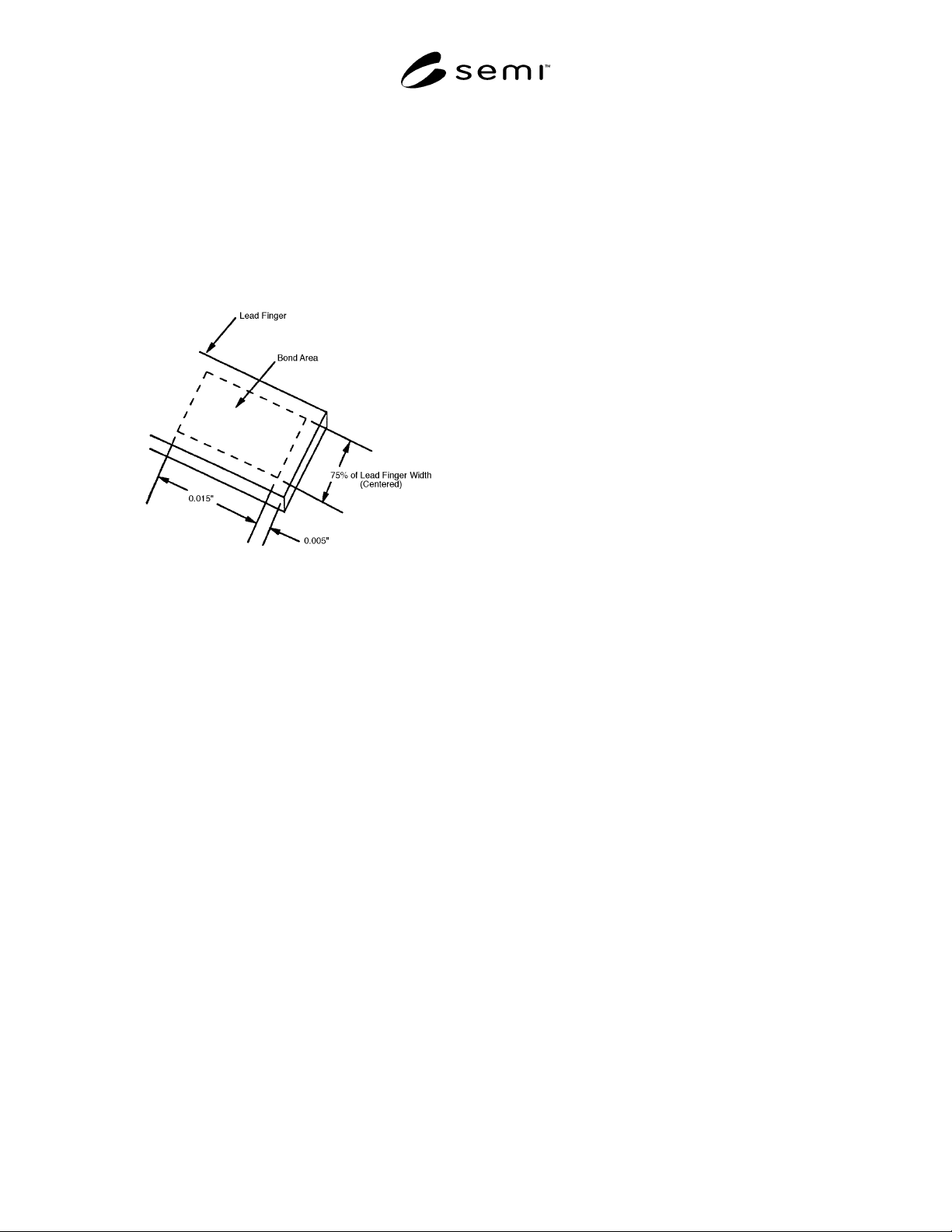
9.4.1 Lead Bond Areas — The minimum lead bond
area on the lead tip is defined in Figure 4.
Figure 4
9.4.1.1 Voids or Pits — Exposure of base metal with
any dimension greater than 0.001" (0.025 mm).
9.4.1.2 Discoloration, Blistering, or Peeling of the
Metallization
9.4.1.3 Scratches or Scrapes — Any b uild-up of
metallization or exposure of base metal.
9.4.1.4 Foreign Material, Including Glass Splatter or
Projections — No more than three sites, each with a
maximum dimension in any plane of 0.001" (0.025
mm).
9.4.1.5 Glass Wetting or Cracking — For purchased
sub-assemblies, any lead finger which is not firmly
embedded in the glass.
9.4.1.6 Glass Pullback from the Lead Tip — 0.010"
(0.254 mm) maximum.
9.4.1.7 Glass Bulge between Lead Fingers (Purchased
or In-House Sub-Assemblies) — 0.005" (0.127 mm)
height above the fingers except as agreed upon between
user and supplier for narrow pitch leads where this limit
may cause wire bond interference problems.
9.4.1.8 Lead Tip Coplanarity — 0.006" (0.15 mm)
maximum allowable difference in the position of the
top surface of the lead from highest lead to lowest lead.
9.4.1.9 Lead Tip Pitch — ± 0.002" (0.508 mm)
maximum allowable variation from true position.
9.4.2 Internal Lead Areas, Excluding Lead Bond
Areas
9.4.2.1 Burrs, Projections, and Pits — 0.002"
(0.508 mm) maximum allowable depth or height.
9.4.2.2 Foreign Material, Including Plating
Discoloration — 0.015" (0.381 mm) maximum surface
dimension or exceeding 0.002" (0.508 mm) in height.
9.4.2.3 Voids — Any exposure of base metal with a
major dimension greater than 0.002" (0.508 mm).
9.4.2.4 Blistering or Peeling of Metallization
9.4.2.5 Scratches and Scrapes — Any build-up of
metallization or exposure of base metal.
9.4.3 External Lead Areas — Unplated
NOTE 7: Non-functional areas of the leadframe, such as tie
bars, shall not be subjected to inspection unless they interfere
with handling equipment.
9.4.3.1 Scratches — Any scratch causing a loss of
more than 25% of the leadframe thickness.
9.4.3.2 Voids — Any void which violates the criteria
of Section 9.4.3.1 or causes a loss of more than 10% of
the design width of a leadframe detail.
9.4.3.3 Burrs — In excess of 0.002" (0.051 mm) in
height and 0.005" (0.127 mm) in the major dimension.
9.4.4 External Leads — Plated
NOTE 8: Non-functional areas of the leadframe, such as tie
bars, shall not be subjected to inspection unless they interfere
with handling equipment.
9.4.4.1 Scratches — Any scratch causing a loss of
more than 25% of the leadframe thickness.
9.4.4.2 Voids — Any void which violates the criteria
of Section 9.4.3.1 or causes a loss of more than 10% of
the design width of leadframe detail.
9.4.4.3 Burrs — In excess of 0.002" (0.051 mm) in
height and 0.005" (0.127 mm) in the major dimension.
9.4.4.4 Scratches and Scrapes — Any exposure of the
base metal or loss of plating integrity over more than
5% of a lead finger.
9.4.4.5 Voids — Any exposure of base metal.
9.4.4.6 Blistering or Peeling
9.4.5 Leadframe/Base/Window Assembly
9.4.5.1 Lead Tip Overhang — 0.010" (0.254 mm)
maximum from the cavity wall (see Figure 5).