semi合集-English.pdf - 第966页
SEMI E129-1103 © SEMI 2003 4 5.1.6 ESD simulator — an instrument providing a specified electrostatic di scharge curre nt waveform when discha rged directly t o a product or equipm ent part. 5.1.7 facility electrostatic l…

SEMI E129-1103 © SEMI 2003 3
ESD ADV1.0 — Glossary of Terms
ESD ADV53.1 — ESD Protective Workstations
ESD S6.1 — Grounding – Recommended Practice
ESD SP10.1 — Automated Handling Equipment
ESD STM11.11 — Surface Resistance Measurement of
Static Dissipative Planar Materials
ESD STM5.1 — Electrostatic Discharge Sensitivity
Testing – Human Body Model
ESD STM7.1 — Floor Materials – Resistive
Characterization of Materials
ESD STM97.2 — Floor Materials and Footwear
Voltage Measurement in Combination with a Person
ESD TR11-01 — Electrostatic Guidelines and
Considerations for Cleanrooms and Clean
Manufacturing
ESD TR20.20 — ESD Handbook
4.3 IEC Documents
2
IEC 61000-4-2 — Electromagnetic compatibility
(EMC) Part 4.2: Testing and measurement techniques
– Electrostatic discharge immunity test, Transient
Immunity Standard, International Electrotechnical
Commission (IEC).
IEC EN 61340-5-1 — Electrostatics – Part 5.1:
Protection of electronic devices from electrostatic
phenomena — General Requirements.
NOTE 2: This replaces CENNELEC 100015-1 — Elements
of a Static Control Program
IEC EN 61340-5-2 — Electrostatics – Part 5.2:
Protection of electronic devices from electrostatic
phenomena – Users’ Guide – Elements of a Static
Control Program
4.4 JEDEC Documents
3
JESD22-A114 — Electrostatic Discharge (ESD)
Sensitivity Testing Human Body Model (HBM)
JESD22-C101 — Field-Induced Charged-Device
Model Test Methods for Electrostatic Discharge
Withstand Thresholds of Microelectronic Components
JESD625 — Requirements for Handling Electrostatic-
Discharge-Sensitive (ESDS) Devices
2 IEC, 3, Rue de Varembe, CH - 1211 Geneva 20
Switzerland (
www.IEC.org.ch)
3 JEDEC, 2500 Wilson Blvd., Arlington, VA 22201-3834, USA
(
www.jedec.org)
4.5 Other Documents
89/336/EEC — Directive on Electromagnetic
Compatibility – European Commission
4
BS EN 50082-2 — Electromagnetic Compatibility
(EMC). Generic Immunity Standards. Immunity for
Industrial Environments, British Standards Institution
(BSI)
5
ITRS 2003 — International Technology Roadmap for
Semiconductors – International SEMATECH
6
MIL-STD 883 — Test Method Standard –
Microcircuits (Method 3015.7 – Electrostatic Discharge
Sensitivity Classification), Defense Supply Center
Columbus
7
NOTICE: Unless otherwise indicated, all documents
cited shall be the latest published versions.
5 Terminology
5.1 Definitions
5.1.1 carrier — a device for holding wafers, dies,
packaged integrated circuits, or reticles for various
processing steps in semiconductor manufacturing (from
SEMI E78).
5.1.2 electromagnetic interference (EMI) — any
electrical signal in the non-ionizing (sub-optical)
portion of the electromagnetic spectrum with the
potential to cause an undesired response in electronic
equipment.
5.1.3 electrostatic attraction (ESA) — the force
between two or more oppositely charged objects.
NOTE 3: The result is increased deposition rate of particles
onto charged surfaces, or movement of charged materials.
5.1.4 electrostatic compatibility — charge control
adequate to allow the manufacturing of products and
the inter-equipment transfer of products, reticles, and
carriers without electrostatic problems.
5.1.5 electrostatic discharge (ESD) — the rapid
spontaneous transfer of electrostatic charge induced by
a high electrostatic field.
NOTE 4: Usually the charge flows in a spark between two
objects at different electrostatic potentials.
4 European Commission, Rue de la Loi, Wetstraat 200, B-1049
Brussels, Belgium (
www.europa.eu.int)
5 BSI, 389 Chiswick High Road, GB - LONDON W4 4AL
(
www.BSI-global.com)
6 International SEMATECH, 2706 Montopolis Drive, Austin, TX
78741, USA (
www.sematech.org)
7 Defense Supply Center Columbus, P.O. Box 3990, Columbus, OH
43216-5000, USA (
www.dscc.dla.mil)

SEMI E129-1103 © SEMI 2003 4
5.1.6 ESD simulator — an instrument providing a
specified electrostatic discharge current waveform
when discharged directly to a product or equipment
part.
5.1.7 facility electrostatic levels — acceptable static
charge levels related to the major technology nodes of
product and reticle feature sizes.
5.1.8 minienvironment — a localized environment
created by an enclosure to isolate the product from
contamination and people.
5.1.9 product — any unit intended to become a
functional semiconductor device.
6 Requirements
6.1 Measurement Methods and Instrumentation — No
single method of testing for static charge can determine
a “safe” level. The amount of static charge, the
distribution of static charge on an object, and the nature
of the static discharge will all interact to determine if
the charge level is safe. It will be difficult to determine
levels that guarantee static related problems are totally
eliminated. The goals of this guide are to assist the user
in identifying static charge levels likely to cause
problems in the semiconductor manufacturing facility,
and to direct the user to static control methods
appropriate to mitigate these problems. This guide is
intended to provide the user with enough insight to
define test methodologies for measuring static charge
and for evaluating the methods to control it.
6.2 ESD Damage — Direct Discharge
6.2.1 When considering direct ESD damage to an
object (e.g., product, reticle, or equipment), the
important parameter is the current accompanying the
charge transfer to or from the object. The charge may
be transferred from facility and furniture surfaces,
personnel, equipment parts, carriers, packaging
materials, or anything else that contacts the object.
6.2.2 Established test methods exist for determining the
threshold of damage to a particular object. When testing
packaged devices, ESD simulators of various types are
used
. Refer to ESD Association standards ESD
STM5.1, ANSI ESD STM5.2, and ANSI ESD
STM5.3.1, JEDEC JESD22-A114 and JESD22-C101,
or MIL-STD 883 for further information concerning
device testing. There are no established standards for
ESD simulator testing of wafers, reticles, or
unpackaged semiconductor devices. ESD damage
thresholds for these items may be significantly different
than for packaged devices.
6.2.3 Once the damaging current level for a product is
determined using an appropriate ESD simulator, the
corresponding amount of charge is known from the
ESD simulator operating parameters.
6.2.4 In the manufacturing facility, it is important to
know the charge on any objects that might directly
contact the product. Charge measurement methods
using a coulombmeter and Faraday Cup are described
in SEMI E78 and SEMI E43 for isolated conductors
(including personnel), or small and moveable objects.
The measurement methods of SEMI E43 can be used to
establish that the charge levels on these objects will
pose a hazard to products or reticles from a direct ESD
event.
6.2.5 Electric field measurements on large and fixed
objects, or insulators are less useful in estimating
whether or not a damaging direct ESD event will occur.
On objects that cannot be conveniently measured with a
coulombmeter, Electrostatic Fieldmeter measurements
can be useful in estimating the ESD threat, even though
the measurement may be less quantitative than the
coulombmeter measurement.
6.3 ESD Damage — Induced Charge
6.3.1 Charge may be induced on an object that results
in ESD damage. Part of a product (e.g., epoxy
package) or reticle (e.g., quartz substrate) may become
charged and induce charge separation to occur on
another part of the product (e.g., lead pins) or reticle
(e.g., chrome traces). ESD will occur if the lead pins or
chrome traces contact ground. Using a coulombmeter
or Faraday Cup and the methods of SEMI E43, the end
user should test product or reticles to determine the
level of static charge at which ESD damage occurs.
6.3.2 Alternatively, either the product or reticles may
be handled in proximity to another charged object. The
field from this charged object induces charge on
product or reticles, and ESD can result if the product or
reticle contacts ground while in the presence of the
field. Using an electrostatic fieldmeter and the methods
of SEMI E43, the end user should test products and
reticles to determine the acceptable levels of electric
field from static charge.
6.3.3 It has been shown that a changing electric field
causes ESD damage to reticles without ground contact
occurring. A changing electric field can result at the
reticle when an object in proximity to the reticle
acquires a charge, the reticle or a charged object are in
motion with respect to each other, or grounding
conditions change the field between a charged object
and the reticle (for example, due to robot handling).
See references in Related Information 2. In areas of the
manufacturing facility that produce or handle reticles,
electric field from any charged object will need to be
limited to levels that do not cause reticle ESD damage.
Test methods for electric field are contained in SEMI
SEMI E129-1103 © SEMI 2003 5
E43. There are currently no industry standards for
determining the electric field sensitivity of reticles, but
test methods do exist.
6.3.4 Finally, there is increasing anecdotal evidence
that the presence of static charge on wafer surfaces is
becoming an ESD hazard as gate oxide thicknesses
become thinner. In the future, there may need to be
further limits on allowable static charge on wafer
surfaces to prevent ESD-related gate oxide damage
during front-end semiconductor manufacturing. Further
research is needed in this area.
6.4 Particle Attraction
6.4.1 Electrostatic attraction (ESA) of particles can
occur due to the electrostatic field created by the charge
on the surface of an object. Refer to SEMI E78 and
SEMI E43 for an analysis of this effect and its
measurement methods.
6.4.2 Particles may be attracted to charged facility
surfaces, or directly to charged products or reticles.
Subsequently, they may be dislodged from facility
surfaces and transfer to products or reticles. Once on
products or reticle surfaces they may cause either
random or repeating defects.
6.4.3 Electrostatic particle deposition velocity depends
only on electric field, particle size and particle charge.
However, the number of particles deposited on a
surface also depends on the particle concentration in the
area and the length of the exposure time during which
particle deposition occurs. SEMI E78 contains
information to relate allowable electric field to ambient
particle concentration and exposure time.
6.4.4 The measurement methods of SEMI E43 can be
used to establish that the electric field from any facility
surface meets the requirements of this document.
6.4.5 Charge is difficult to evaluate on large objects,
especially insulators. Electric field measurements on
these objects may be useful in estimating the risk that a
damaging direct ESD event might occur. However,
electric field measurements on insulators are highly
qualitative and only provide a figure of merit as to the
threat that these charges may represent to the ESD-
sensitive device.
6.5 Equipment ESD
6.5.1 Equipment ESD immunity has been established
at levels considerably higher than those that result in
damage to product and reticles. If facility static charge
limits shown in Table 1, of Section 12.5 are used to
protect product and reticles, they will provide sufficient
protection for the equipment.
6.5.2 Equipment ESD immunity is addressed, in
general, through a number of international standards
including SEMI E78, IEC 61000-4-2, and BS
EN50082-2 for European CE compliance.
Measurements are made using an ESD simulator, which
is described in these standards.
7 Apparatus
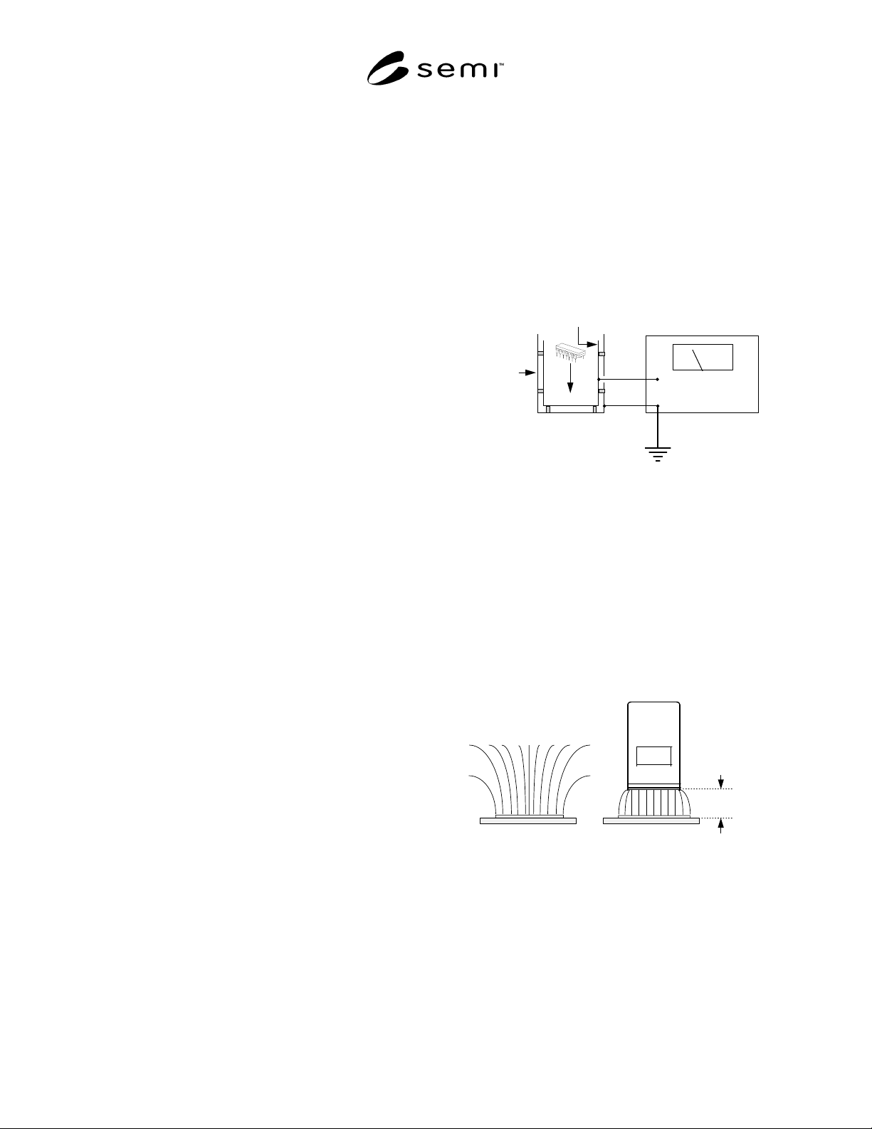
7.1 ESD Damage — For measuring the charge
generated on product, reticles, or carriers, the Faraday
Cup test method is shown in Figure 1. Additional
information on this test method is contained in SEMI
E43.
In
Ground
Electrometer
Faraday
Cup
Isolated
Inner Cup
Shielding
Outer Cup
Figure 1
Faraday Cup Charge Measurement
7.2 When the object whose charge is to be measured is
conductive, a nanocoulombmeter may be used.
Additional information on this test method is contained
in SEMI E43.
7.3 The instrument used for making electrostatic field
measurements on large objects or surfaces is known as
an electrostatic fieldmeter. Instructions concerning its
use should be obtained from the instrument
manufacturer and SEMI E43. The measurement
configuration is shown in Figure 2.
1
9
9
9
+ + + + + + + + + + + + + + + +
2.54 cm
(1 inch)
Electrostatic
Fieldmeter
(volts/cm)
+ + + + + + + + + + + + + + + +
Charged
Surface
Electric Field Lines
Charged
Surface
Figure 2
Electrostatic Field Measurement
7.4 For small objects or surface areas, an electrostatic
voltmeter is appropriate.