semi合集-English.pdf - 第4585页
SEMI D34-0703 © SEMI 2003 3 5.5.3.2 Measurement Conditions 5.5.3.2. 1 Equipm ent: Spectrophotometer 5.5.3.2. 2 Measurement Wavelengt h: 400–700 nm (10 nm interva ls) 5.5.4 Definition and Me asurement Method for Transmitt…
SEMI D34-0703 © SEMI 2003 2
5.1.2 Defect Measurement (Inspection) Method —
Observe defects under fluorescent light (600–1600 lux),
using either reflection, transmission, or Cross-Nicol
transmission inspection, or a combination of the above,
at approximately 30 cm from the sample.
5.1.2.1 Reflection Inspection: Conduct on a
blackboard, using fluorescent light.
5.1.2.2 Transmission Inspection: Conduct on a
backlight
5.1.2.3 Cross-Nicol: Place a reference polarizing film
on a backlight, and conduct transmission inspection in
transmission inspection Cross-Nicol state.
5.2 Polarizing Film Visual Appearance (Line Defects)
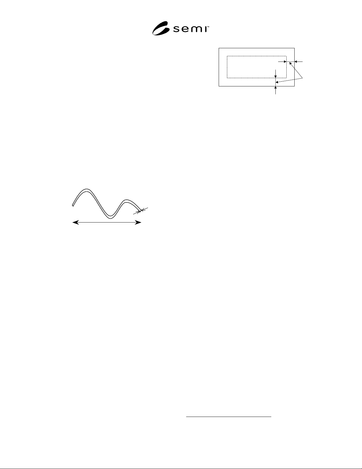
5.2.1 Defect Size Definition
5.2.1.1 Line defects visually detected during reflection,
transmission, or Cross-Nicol inspection. Size is defined
by measuring the length of the long side and short side.
W
L
Figure 2
Definition of Defect Size (Line Defect)
5.2.2 Defect Measurement (Inspection) Method —
Observe defects under fluorescent light, using either
reflection, transmission, or Cross-Nicol transmission
inspection, or a combination of the above, at
approximately 30 cm from the sample.
5.2.2.1 Reflection Inspection: Conduct on a
blackboard, using fluorescent light.
5.2.2.2 Transmission Inspection: Conduct on a
backlight
5.2.2.3 Cross-Nicol: Place a reference polarizing film
on a backlight, and conduct transmission inspection in
transmission inspection Cross-Nicol state.
5.3 Polarizing Film Visual Appearance (Visual
Exclusion Area)
5.3.1 Definition
5.3.1.1 L of the Visual Exclusion Area is the
measurement of the distance from each side of the
polarizing film.
L
Figure 3
Definition of Visual Exclusion Area
5.4 Polarizing Film Thickness
5.4.1 Thickness Definition
5.4.1.1 Thickness, excluding the thickness of
protective film and separate film.
5.4.2 Thickness Measurement Method
5.4.2.1 Measured using a thickness gauge that can
measure to 0.001 mm.
5.5 Polarizing Film Optical Characteristics
5.5.1 Definition of Single Transmittance (Ty) and
Measurement Method
5.5.1.1 Value of Transmittance of 1 polarizing film,
visibility corrected (JIS Z8701) by supplementary
standard illuminant C (JIS Z8720)
7
, 2° range of view.
5.5.1.2 Measurement Conditions
5.5.1.2.1 Equipment: Spectrophotometer
5.5.1.2.2 Measurement Wavelength: 400–700 nm
(10 nm intervals)
5.5.2 Definition and Measurement Method of Parallel
Transmittance (T
//
)
5.5.2.1 Value of Transmittance of 2 polarizing films
placed parallel Nicol, visibility corrected (JIS Z8701)
by supplementary standard illuminant C (JIS Z8720),
2° range of view.
5.5.2.2 Measurement Conditions
5.5.2.2.1 Equipment: Spectrophotometer
5.5.2.2.2 Measurement Wavelength: 400–700 nm
(10 nm intervals)
5.5.3 Definition and Measurement Method for Cross
Transmittance (T
⊥
)
5.5.3.1 Value of Transmittance of 2 polarizing films
placed crossed Nicol, visually corrected (JIS Z8701) by
supplementary standard illuminant C (JIS Z8720), 2°
range of view.
7 Commonly known as “Light Source C”. Abbreviated to “Ill.C”.
SEMI D34-0703 © SEMI 2003 3
5.5.3.2 Measurement Conditions
5.5.3.2.1 Equipment: Spectrophotometer
5.5.3.2.2 Measurement Wavelength: 400–700 nm
(10 nm intervals)
5.5.4 Definition and Measurement Method for
Transmittance of each Wavelength
5.5.4.1 Measured value of 1 polarizing film at specific
wavelengths (440 nm, 550 nm, 610 nm)
5.5.4.2 Measurement Conditions
5.5.4.2.1 Equipment: Spectrophotometer
5.5.4.2.2 Measurement Wavelength: 440 nm, 550 nm,
610 nm
5.5.5 Definition and Measurement Method of UV Cut
Performance
5.5.5.1 Transmittance of 1 polarizing film, measured at
380 nm, is defined as UV cut performance.
5.5.5.2 Measurement Conditions
5.5.5.2.1 Equipment: Spectrophotometer
5.5.5.2.2 Measurement Wavelength: 380 nm
5.5.6 Definition and Measurement Method of
Polarization Efficiency (Py)
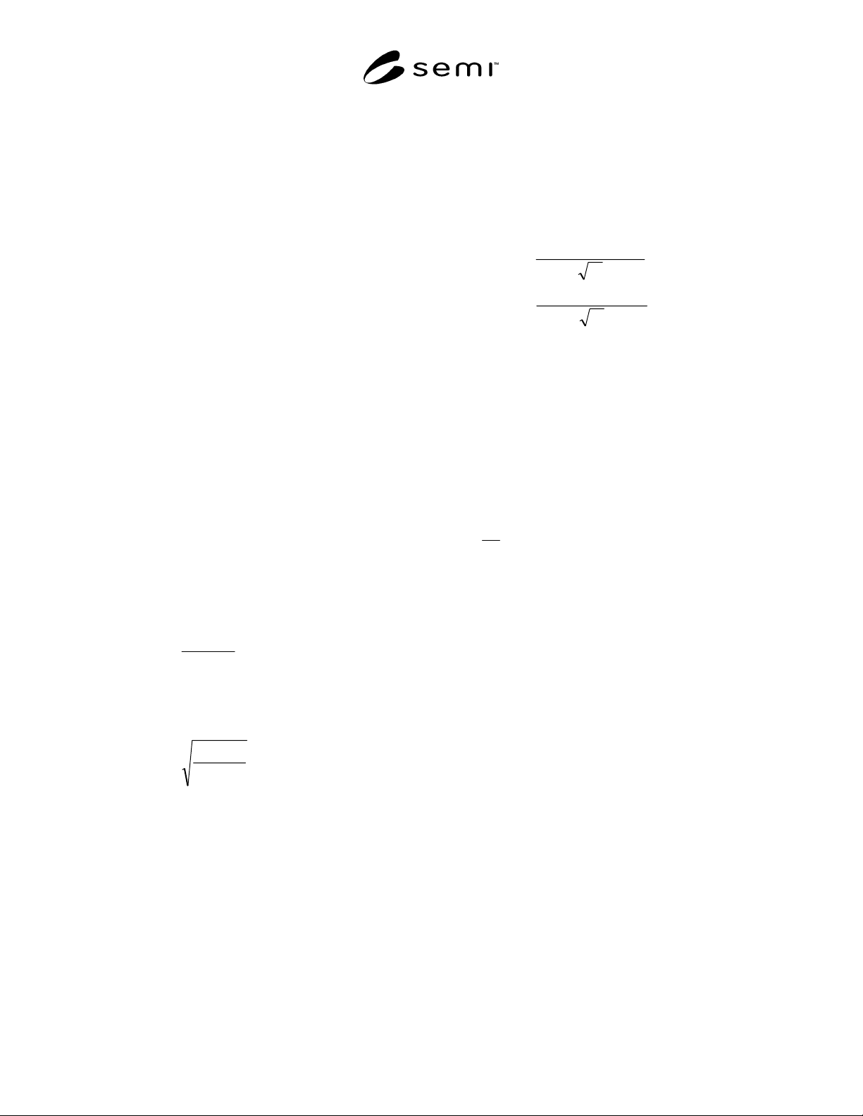
5.5.6.1 Expressed using the following formula, where
T
A
is transmittance (visibility corrected) on the
absorption axis, and T
B
is transmittance (visibility
corrected) on the transmittance axis.
AB
AB
TT
TT
Py
+
−
=
×100 (%)
5.5.6.2 The same value from the above equation can
also be calculated using the below equation, where T
//
is parallel transmittance and T
⊥
is cross transmittance.
⊥
⊥
+
−
=
TT
TT
Py
//
//
×100 (%)
5.5.6.3 Measurement Conditions
5.5.6.3.1 Equipment: Spectrophotometer
5.5.6.3.2 Measurement Wavelength: 400–700 nm
(10 nm intervals)
5.5.7 Definition and Measurement Method for Hue a*,
b*
5.5.7.1 Polarizing film transmittance value calculated
in accordance with JIS Z8729.
5.5.7.2 Measurement Conditions
5.5.7.2.1 Equipment: Spectrophotometer
5.5.7.2.2 Measurement Wavelength: 400~700 nm (10
nm intervals)
5.5.8 Definition and Measurement Method for Hue a, b
5.5.8.1 Visibility corrected (JIS Z8701) value by
supplementary standard illuminant C (JIS Z8720), 2°
range of view, calculated using the tristimulus values
(X, Y, Z) from the below formula.
(
)
Y
YX02.15.17
a
−
=
(
)
Y
Z847.0Y0.7
b
−
=
5.5.8.2 Measurement Conditions
5.5.8.2.1 Equipment: Spectrophotometer
5.5.8.2.2 Measurement Wavelength: 400–700 nm
(10 nm intervals)
5.5.9 Definition and Measurement Method for Haze
5.5.9.1 Scattered transmittance and all line
transmittance, measured using integrated sphere light
transmittance measurement equipment, expressed as a
ratio.
H =
t
d
T
T
×100 (%)
T
d
: Scattered Transmittance(%)
T
t
: All line transmittance(%)
To be measured in accordance with JIS K7105.
6 Equipment
6.1 Spectrophotometer with the below performance
shall be used.
6.1.1 Optical Wavelength: Sub 10 nm analysis
capability, adjustable between 380–780 mm.
7 Equipment Calibration
7.1 Equipment shall be calibrated in accordance with
the manufacturer’s manual.
7.2 When, due to calibration, there is a change in the
equipment’s performance, for example, linearity, phase
deviation, etc., a record shall be kept.
8 Related Document
8.1 Measurement Method for Optical Characteristics of
Polarizing Films Using Crystal Rotation Method

SEMI D34-0703 © SEMI 2003 4
NOTICE: SEMI makes no warranties or
representations as to the suitability of the standards set
forth herein for any particular application. The
determination of the suitability of the standard is solely
the responsibility of the user. Users are cautioned to
refer to manufacturer's instructions, product labels,
product data sheets, and other relevant literature,
respecting any materials or equipment mentioned
herein. These standards are subject to change without
notice.
By publication of this standard, Semiconductor
Equipment and Materials International (SEMI) takes no
position respecting the validity of any patent rights or
copyrights asserted in connection with any items
mentioned in this standard. Users of this standard are
expressly advised that determination of any such patent
rights or copyrights, and the risk of infringement of
such rights are entirely their own responsibility.