semi合集-English.pdf - 第4187页
SEMI F71-1102 © SEMI 2002 2 7.2 Perform the helium leak test and confirm whether there is leakage in the gas panel before start ing temperature cycle examination. Connect all flow pat h in the gas panel to h elium leak d…

SEMI F71-1102 © SEMI 2002 1
SEMI F71-1102
TEST METHOD FOR TEMPERATURE CYCLE OF GAS DELIVERY
SYSTEM
This guideline was technically approved by the Global Facilities Committee and is the direct responsibility of
the Japan Facilities Committee. Current edition approved by the Japan Regional Standards Committee on
July 19, 2002. Initially available at www.semi.org September 2002; to be published November 2002.
1 Purpose
1.1 The purpose of this document is to provide a
standardized methodology and procedure for the
leakage performance of gas delivery systems
temperature cycling.
2 Scope
2.1 This test method applies to gas delivery systems
installed in semiconductor manufacturing equipment.
2.2 This standard does not purport to address safety
issues, if any, associated with its use. It is the
responsibility of the users of this standard to establish
appropriate safety health practices and determine the
applicability or regulatory limitations prior to use.
3 Referenced Standards
NOTE 1: As listed or revised, all documents cited shall be the
latest publications of adopted standards.
3.1 SEMI Standards
SEMI F1 — Specification for Leak Integrity of High-
Purity Gas Piping System and Components
4 Terminology
4.1 Definitions
4.1.1 gas delivery system — A system installed in
semiconductor manufacturing equipment to deliver
process and carrier gases to reactors, which typically
consists of tubing, fittings, valves, filters, mass flow
controllers and regulators.
4.1.2 Helium leak test — Testing shall be conducted
per procedure outlined of inboard leak test in SEMI F1.
4.1.3 T-max — The maximum set temperature of the
temperature cycle test.
4.1.4 T-min — The minimum set temperature of the
temperature cycle test.
5 Apparatus
5.1 helium leak detector — The detector has
appropriate detection sensitivity according to SEMI F1.
5.2 constant temperature oven — The constant
temperature oven should have the capacity to
accommodate the test configuration and maintain the
elevated T-max temperature to ± 5° C.
5.3 freezer — The freezer should have the capacity to
accommodate the test configuration and maintain the T-
min temperature to ± 5° C.
5.4 thermocouple — The thermocouple should make
contact with the sample and should take measures of a
noise.
6 Test Specimen and Condition
6.1 The temperature cycling test should be performed
using a typical gas delivery system configuration. An
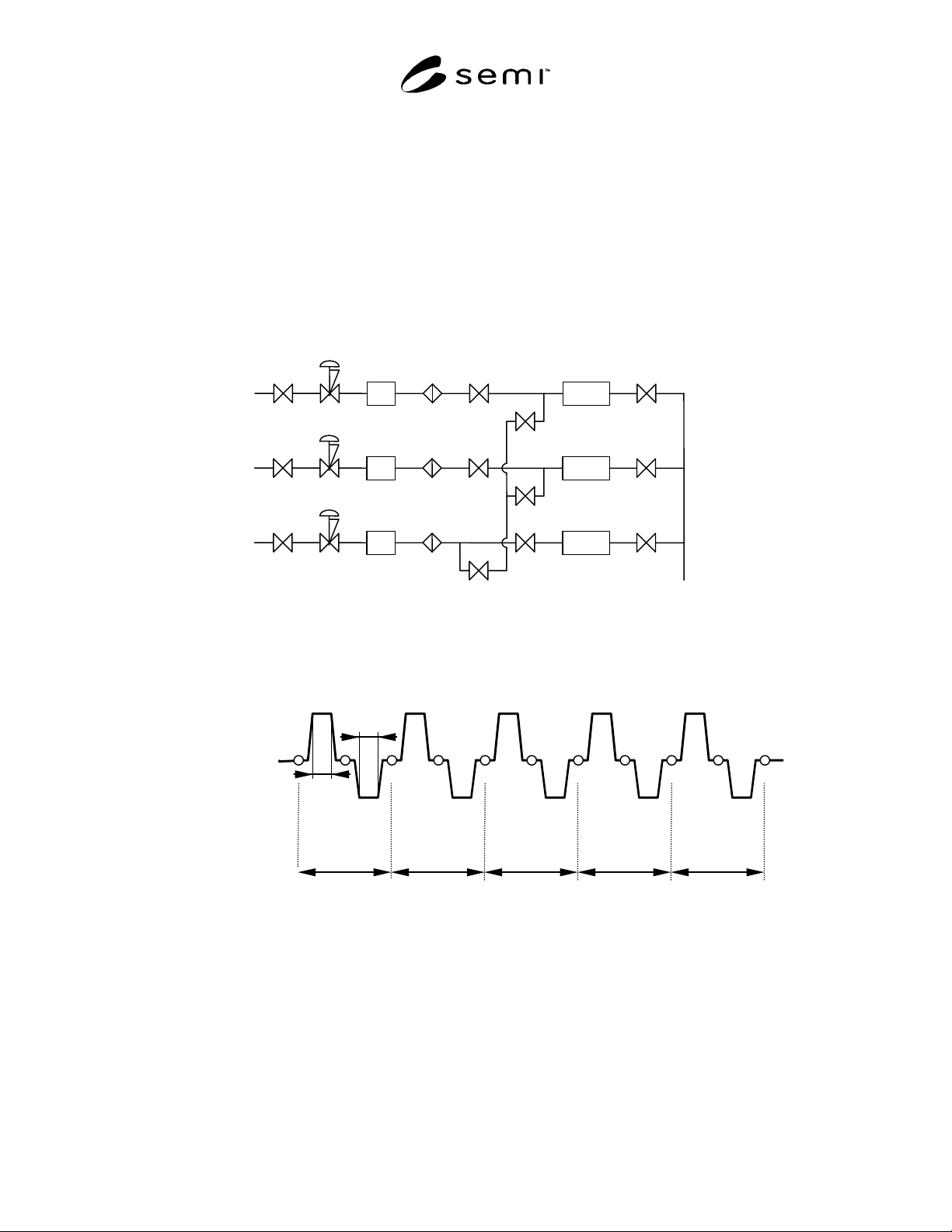
example is shown in Figure 1.
6.1.1 The influence of heat expansion is not easily
measured with a single component. Therefore, use a
gas panel having a minimum of three lines as an
assembled sample. An example is shown in Figure 1.
6.2 A set temperature (T-max, T-min) at the
temperature cycle must be within the range of the rated
temperature of components used in the gas panel.
6.3 The sealing surface used in the gas delivery system
shall not have any scratches or other defects which are
visible to non-magnified normal vision.
6.4 Install the thermocouple in approximately the
center of the gas panel to be tested.
6.5 The user can arbitrarily decide heating and cooling
temperatures in temperature cycle examination
according to the purpose of use.
6.6 The helium leak test shall be performed only at
room temperature (22 ± 4° C), not during heating or
cooling.
7 Procedure
7.1 A typical gas delivery system configuration is
shown in Figure 1. The following test procedure shall
be interpreted to apply to the actual test target and
deviations from the procedure in this document shall be
recorded along with the test results. (The condition of
heated T-max and cooling T-min was taken up here as
an example.)
SEMI F71-1102 © SEMI 2002 2
7.2 Perform the helium leak test and confirm whether
there is leakage in the gas panel before starting
temperature cycle examination. Connect all flow path
in the gas panel to helium leak detector and plug all
open end connections before the helium leak test is
executed. Abort testing if leakage is detected and record
leaking points and leak rate.
7.3 Put the test sample in the constant temperature
oven and apply heat until the test sample reaches T-
max. Maintain the temperature for 10 ± 1 minutes.
7.4 Remove the sample from the constant temperature
oven and cool down to the room temperature and
perform helium leak test.
7.5 Put the test sample in the freezer and cool until the
test sample reaches T-min. Maintain the temperature
for 10 ± 1 minutes.
7.6 Remove the sample from the freezer and
equilibrate to the room temperature and perform helium
leak test .
7.7 Repeat Section 7.2 through 7.6 for 5 cycles. The
temperature cycles should be recorded and plotted as
shown in Figure 2.
MFCPT
MFCPT
MFCPT
Figure 1
Typical Gas Delivery System Configuration
R.T. (22 ± 4)
T-max
T-min
10 M
10 M
1 cycle 3 cycle 5 cycle 2 cycle 4 cycle
Figure 2
Temperature Cycle Chart

SEMI F71-1102 © SEMI 2002 3
8 Reporting Results
8.1 The report shall include the following:
• Date and time of test,
• Operator,
• Leak point and leak rate,
• Helium leak detector maker and model number,
• Flow diagram of the test gas panel and layout
drawing,
• Schematic of the test system,
• Temperature conditions of the temperature cycle
test, and
• Any deviations from the test procedure in section
7.
A sample report format is given in Appendix 1.