semi合集-English.pdf - 第6891页
SEMI S6-93 © SEMI 199 3 1 SEMI S6-93 SAFETY GUIDELINE FOR VENTILATION NOTICE: This gu ideline does not pu rport to address all of the safety issues associated with its use. It is the responsibility of t he user of this g…
SEMI S5-0703 © SEMI 1993, 2003 5
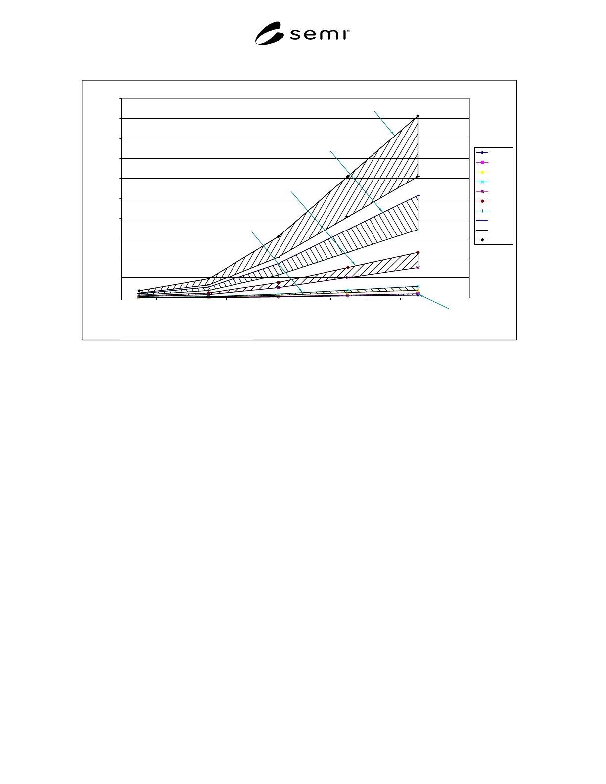
Figure 1 Nitrogen Flow Rate
0
200
400
600
800
1000
1200
1400
1600
1800
2000
700 2100 7000 14000 21000
Cylinder Pressure (kPa)
Nitrogen Flow Rate (slm)
0.15 lo
0.15 hi
0.25 lo
0.25 hi
0.50 lo
0.50 hi
0.75 lo
0.75 hi
1.00 lo
1.00 hi
1.00 mm equiv. orifice
0.75 mm equiv. orifice
0.50 mm equiv. orifice
0.25 mm equiv. orifice
0.15 mm equiv. orifice
Figure 1
Nitrogen Flow Rate
NOTICE: SEMI makes no warranties or representations as to the suitability of the standards set forth herein for any
particular application. The determination of the suitability of the standard is solely the responsibility of the user.
Users are cautioned to refer to manufacture's instructions, product labels, product data sheets, and other relevant
literature, respecting any materials or equipment mentioned herein. These standards are subject to change without
notice.
The user’s attention is called to the possibility that compliance with this standard may require use of copyrighted
material or of an invention covered by patent rights. By publication of this standard, SEMI takes no position
respecting the validity of any patent rights or copyrights asserted in connection with any item mentioned in this
standard. Users of this standard are expressly advised that determination of any such patent rights or copyrights, and
the risk of infringement of such rights, is entirely their own responsibility.
Copyright by SEMI® (Semiconductor Equipment and Materials
International), 3081 Zanker Road, San Jose, CA 95134. Reproduction o
f
the contents in whole or in part is forbidden without express written
consent of SEMI.

SEMI S6-93 © SEMI 19931
SEMI S6-93
SAFETY GUIDELINE FOR VENTILATION
NOTICE: This guideline does not purport to address
all of the safety issues associated with its use. It is the
responsibility of the user of this guideline to establish
appropriate safety and health practices and determine
the applicability of regulatory limitations prior to use.
NOTE: As listed or revised, all documents cited shall be the
latest publications of adopted standards.
1 Introduction
The equipment supplier should design an internal
equipment exhaust system that is efficient when
connected to potential users’ exhaust systems. Seldom,
if ever, are users’ systems designed for a specific piece
of process equipment or set of process equipment. Most
users’ exhaust systems are designed and installed to
industry-accepted exhaust principles.
2 Purpose
This document is intended to help the semiconductor
equipment supplier design equipment exhaust systems
to a common set of performance criteria as well as to
provide assistance to both users and suppliers in the
understanding of exhaust requirements for equipment
systems. It is not intended to establish design
specifications. The supplier will still own, and be
responsible for, the information it specifies. This
guideline has six concurrent performance-related
objectives.
2.1 Ensure hazardous gases, fumes, and vapors are
controlled (during normal operations of equipment and
facilities services) such that concentrations present in
the work room air should be less than 1.0% of the
Threshold Limit Value (TLV), as established by the
American Conference of Governmental Industrial
Hygienists (ACGIH) or Permissible Exposure Limit
(PEL) as published by the appropriate regulatory
agency, whichever is lower.
2.2 Ensure exhaust is provided within specifications to
support the proper operation of equipment.
2.3 Optimize the user’s exhaust system(s).
2.4 Use the most cost effective methods to interface
with user’s exhaust systems.
2.5 Provide a platform for communicating “special
case” exhaust requirements.
2.6 Establish guidelines for measurement and
communication of equipment exhaust requirements.
3 Scope
This guideline applies to all semiconductor equipment
that incorporates exhausted enclosures that are intended
to be connected to user facilities’ exhaust system(s).
This document is written with the assumption that the
users’ exhaust distribution systems will be designed
with central fans, ducting, and, where applicable,
abatement equipment. Where users use other types of
exhaust systems, equipment suppliers should acquire
exhaust specifications from the users. Whether
equipment is connected to a central exhaust system or
to one which serves only that piece of equipment, this
guideline should be applied.
4 Referenced Documents (s ee Appendix 2)
5 Terminology
5.1 balancing — Adjustments made after the
ventilated equipment and the ventilation system are
installed to assure that airflow to each piece of
ventilated equipment is within design specifications.
5.2 capture — To entrain undesirable elements (gases,
fumes, vapor, and particles) in the exhaust stream for
removal.
5.3 dilute — To reduce the concentration of
undesirable elements to acceptable levels. Dilution is a
function of flow volume.
5.4 flow velocity (V) — The average speed at which
the effluent stream travels through the exhaust duct. It
is measured in meters per second (m/s) or feet per
minute (fpm).
5.5 flow volume (Q) — The volumetric flow rate of
the effluent stream passing a given location in the
exhaust system per unit of time. It is measured in cubic
meters per second (m
3
/s) or cubic feet per minute (cfm).
5.6 initiate motion — To use an exhaust stream to start
contaminants (or machine parts) moving from a rest
position.
5.7 long radius elbow — An exhaust duct elbow that
has a center line radius 1.5 or more times the duct
diameter.
5.8 set point tolerance — The range (+/-) of static
pressure within which an exhaust enclosure will
perform efficiently and effectively.
5.9 static pressure (SP) — The measure of differential
pressure across the duct wall to the ambient pressure

SEMI S6-93 © SEMI 1993 2
(inside the duct). The unit of measure is pascals (Pa,
Newtons per square meter (N/m
2
)) or inches of water.
5.10 traverse measurements — Multiple air flow
measurements taken at points of equal separation, in a
matrix pattern, along the face plane of an exhaust duct
or opening in an exhaust enclosure.
5.11 vena contracta — A point in a duct where the
diameter of the air stream is smaller than the diameter
of the duct.
6 Attributes of Typical Semiconductor
Facilities’ Exhaust Systems
6.1 A typical semiconductor facility’s exhaust system
has three measurable working elements: (1) flow
velocity, (2) flow volume, and (3) pressure.
6.1.1 Flow Volume is related to the Flow Velocity by
the equation Q = VA. In this equation, Q = volumetric
flow rate, V = average velocity, and A = duct cross
sectional area (m
2
or ft
2
).
6.2 There are three duct pressure measurements
possible: (1) static pressure, (2) velocity pressure, and
(3) total pressure.
6.2.1 In exhaust distribution systems with central fans
and abatement equipment (typical of semiconductor
facilities), exhaust duct pressure (static) upstream of the
fan is less than the ambient pressure outside of the duct.
6.2.2 While Velocity Pressure (VP) and Total Pressure
(TP) provide a more reliable measure of Flow than
Static Pressure, VP and TP are normally not specified
for semiconductor facilities’ exhaust systems; therefore,
they will not be discussed in these guidelines. If more
information is desired on VP or TP, it can be found in
“Industrial Ventilation” (Appendix 2, Reference 1).
7 Exhaust Usage Typical of Semiconductor
Operations
Semiconductor equipment typically uses exhaust to
perform one or more of the following tasks:
7.1 Capture — Capture should occur as close to the
source as practical to prevent exposure of personnel or
products to the undesirable elements.
7.1.1 Capture is a function of Flow Velocity. Chapter
3 of “Industrial Ventilation,” A Manual of
Recommended Practice, 20th Edition, (Appendix 2,
Reference 1) outlines the design principles and required
velocity calculations for proper capture of process
emissions.
7.2 Moving is also a function of Flow Velocity. The
exhaust requirements specified by the equipment
supplier should be adequate to maintain motion of
undesirable elements once they are captured in the
exhaust stream.
7.3 Dilution is a function of Flow Volume. Dilution
may also provide reactive elements to undesirable
elements entrained in the exhaust stream (for example,
air and silane).
7.4 Holding — The movement of the exhaust stream is
often used to activate and hold safety control devices,
such as vane switches or differential pressure gauges in
the active state. Such safety control devices should be
used to sense adequate exhaust pressure or flow to
ensure safe operation of the process equipment.
7.5 Initiation of Motion — The use of exhaust to
intiate motion in the semiconductor industry is a special
case application and should be resolved at the time of
purchase. Most semiconductor-related gases, vapors,
fumes, and fine particles (less than 20 microns in
diameter) move with the air in which they are mixed.
8 Key Elements of Exhaust Specifications
8.1 SEMI S2 establishes specific requirements for
exhaust enclosures of equipment that use hazardous
materials. Access to enclosures serving hazardous
materials requires special design. If there is a potential
for exposure of personnel to hazardous materials when
the access hatch is open, an average face velocity
(measured at the hatch opening) sufficient to capture
the hazardous materials should be maintained in the
hatch opening. (SEMI S2 also has recommendations for
exhaust monitoring and alarms. S2 should be fully
understood before designing exhaust systems for
hazardous materials.)
8.2 Properties of chemicals (density, vapor pressure,
boiling point, flammability, etc.), the state of the
materials within the exhausted enclosure (solid, liquid,
or gas), and conditions such as temperature and
concentration will determine the final design and
exhaust specifications of the equipment enclosure.
Equipment suppliers should use available reference
books and Material Safety Data Sheets (MSDS) to
obtain information on chemical properties. The
equipment’s process requirements will dictate the state
and condition of the material.
8.3 When developing specifications for equipment
exhaust systems to be given to the equipment user,
equipment suppliers should incorporate all of the key
elements that will provide clear and accurate
information. These key elements are:
1. Point of measurement.
2. Duct size at the point of measurement.
3. Flow through the duct.