semi合集-English.pdf - 第1158页
SEMI E5-1104 © SEMI 1982, 2004 100 Figure 4 The Six Possible Handshakes 10.8.1.3 Figure 5 summarizes the interaction of the timers, ha ndshake messages, and the error me ssages in the form of a flow chart. It also ide nt…
SEMI E5-1104 © SEMI 1982, 2004 99
Stream,Function Name (Mnemonic) Direction
S3,F36 Reticle Transfer Job Request Acknowledgement
Description
This message acknowledges the ReticleTransferJobRequest.
Structure
L,2
1. <RPMACK>
2. L,n
1. L,2
1. <ERRCODE
1
>
2. <ERRTEXT
1
>
.
.
n. L,2
1. <ERRCODE
n
>
2. <ERRTEXT
n
>
Exception
None
10.8 Stream 4 Material Control — The material control stream contains the original material control protocol and
the newer protocol which supports SEMI E32.
10.8.1 Original Material Control Protocol — The functions in the material control stream are used to effect the
automatic transfer of material between equipment. A simple handshake is achieved which provides for a variety of
error conditions which gracefully terminate the handshake. Separate messages advise the host of errors and
completed material transfers.
10.8.1.1 Since the handshake and host messages are separate, the handshake may be achieved transparently through
the host or by direct connection between equipment. The host completes the handshake by relaying messages
between the equipment. Only a single port is required on the equipment, and the equipment has a simple message
handling requirement. When a direct connection is desired, at least three ports are required, the receiving equipment
must look like the host with respect to the sending equipment, and message handling in the equipment is
significantly more complicated than in the host-only connection. Nevertheless, the direct connection may still be
chosen in an attempt to provide operation without a host. Since the host is reasonably transparent in the material
handshake, a simple explanation of the handshake may be achieved by just considering the exchange of messages
between the sender, the equipment wanting to get rid of material, and the receiver (the equipment able to accept the
material).
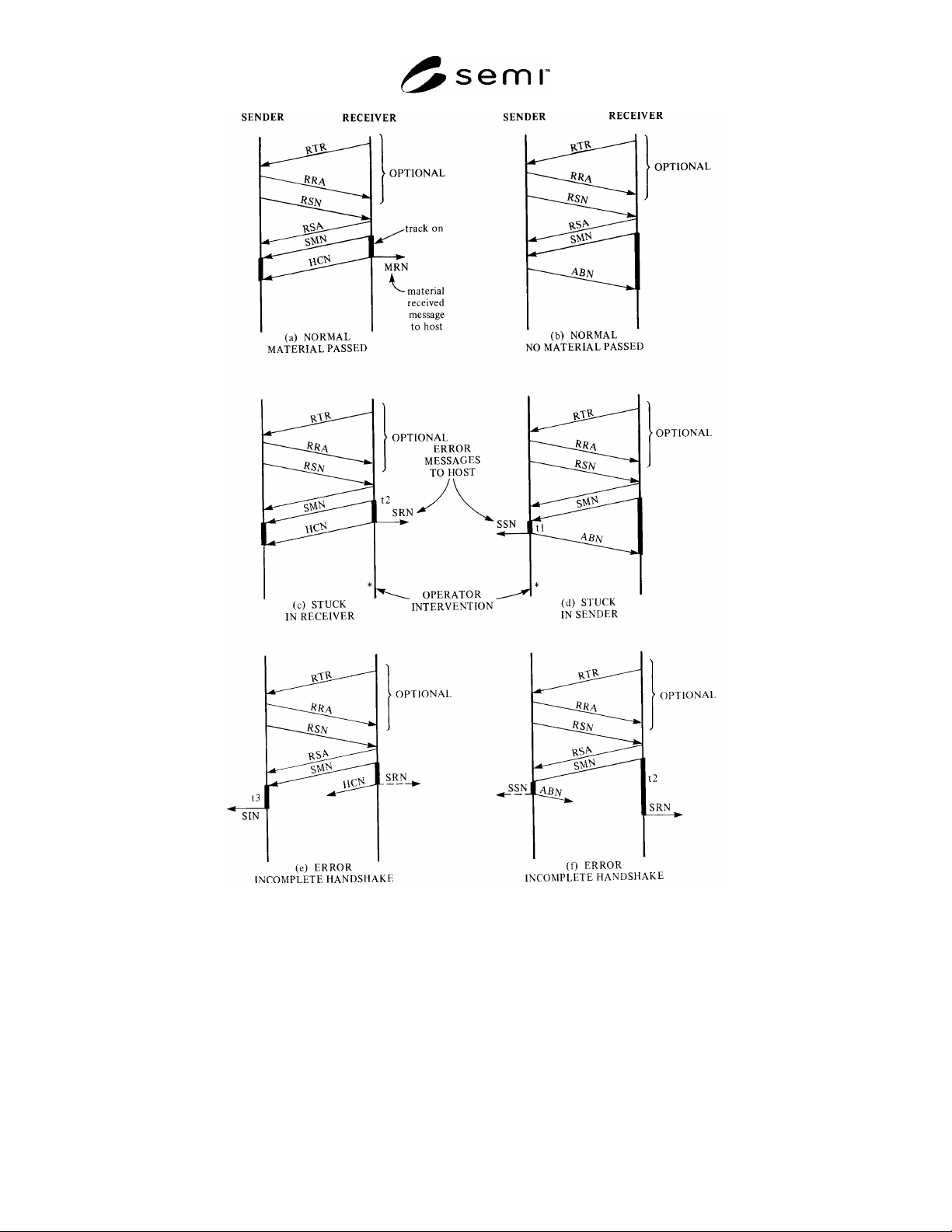
10.8.1.2 Figure 4 shows six possible handshake situations between the sender and the receiver. There are two
normal handshakes. Figure 4(a) shows the normal three-message exchange when material is passed between
equipment. The host is informed of a complete transfer of material. Figure 4(b) shows an alternative message
exchange where the sender changes its mind and decides not to send the material. Figures 4(c) and (d) show two
situations where the material gets stuck during the transfer. In each situation an error message is issued to the host
from the equipment where the material is stuck. The other equipment terminates normally. When material is stuck,
manual intervention is required to move the material towards the equipment which indicates the stuck condition.
The manual intervention has two possible outcomes. One, the material can be moved to a position where the
handshake can resume or, two, the material is broken or lost from the transfer. Lost material causes a lost material
error message to be sent to the host prior to resuming the operation. The specific details of recovering front stuck
material are equipment-dependent. The stuck material condition is determined by the amount of time the material
transfer mechanism is turned on. The sender claims stuck material if the material is not clear of its sensor before a
time t1. The receiver claims stuck material if the material is not received before time t2. Figures 4(e) and (f) show
the possible error conditions in the unlikely event that for some reason a handshake message is lost. Figure 4(e)
shows that time t3 is the longest that the sender will wait for material received message. Times t2 and t3 set an
upper limit on the amount of time either material transport mechanism will operate.
SEMI E5-1104 © SEMI 1982, 2004 100
Figure 4
The Six Possible Handshakes
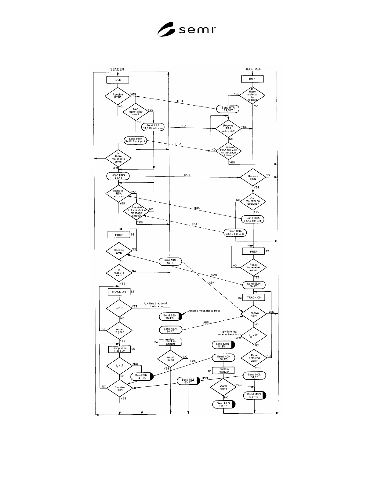
10.8.1.3 Figure 5 summarizes the interaction of the timers, handshake messages, and the error messages in the form
of a flow chart. It also identifies specific states for the sender and the receiver. These states are referred to in the
messages.
The ranges of timer values are as follows:
tl — time to leave sender
tl + 10 <= t2 <= 60 sec. — time to receive
t2 + 10 <= t3 <= 70 sec. — time to complete send
SEMI E5-1104 © SEMI 1982, 2004 101
Default values, tl = 10 sec., t2 = 60 sec., t3 = 70 sec.
NOTE 6: t1, t2, t3 defined for Stream 4 are not to be confused with timeouts T1, T2, T3, and T4 defined in SEMI E4 (SECS-I).
Figure 5
Material Control-Handshake Flowchart