semi合集-English.pdf - 第506页
SEMI E73-0301 © SEMI 1998 , 2001 3 Table 3 Response Time for Signals No. Items Acceptab le Respon se Time Remarks 1 Input Powe r ON Under 10 s econ d s Afte r input power tur n s on Objects: All status signals shall be r…
SEMI E73-0301 © SEMI 1998, 2001 2
atmospheric pressure. They are called dry pumps
because no liquid sealing materials are used on any
surface contacted by gases. Hereafter, the term “DRP”
is substituted for “dry pump”.
5.2 pump alarm A cautionary s ignal that the pump
has stopped.
5.3 pump warning A state of an abnormal or
extraordinary event during pump operation which
means there is a probability the pump will stop.
5.4 vacuum pump A pumping a pparatus which
exhausts gas or air from an enclosed space to achieve a
desired degree of vacuum.
6 Requirements
6.1 Mechanical Interfaces — Table 1 specifies the
required DRP connector type and size by flange/port.
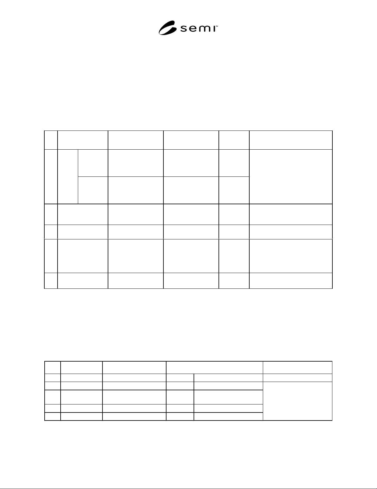
Table 1 Mechanical Connectors
No. Items Connector Type Connector Size
Referenced
Standard
Remarks
Nominal
bore 50 mm
or less
ISO KF flange ≤ 50 mm
Connector dimensions
should be based on the
referenced standard
ISO 2861-1
1Inlet
flange
Nominal
bore over
63 mm size
ISO clamped flange ≥ 63 mm
Connector dimensions
should be based on the
referenced standard
ISO 1609
A port flange which connects the
pump to a process tool to evacuate
gases.
2 Outlet flange ISO KF flange Connector dimensions
should be based on the
referenced standard
ISO 2861-1 A port flange which connects the
pump to the facility evacuation
system.
3 Duct port (Option) Not specified 50 mm or 100 mm
diameter port
Port to connect duct for evacuating
flames inside the pump.
4 Purge gas port Compression type* 1/4" Connector A connection port used to supply
inert gas, typically N
2
, to the pump.
The purge gas protects the inside of
the pump from corrosion due to
process gases.
5 Cooling water port ISO taper pipe thread
(female on pump side)
1/4" or 3/8" ISO 7-1 A connection port to supply water
used to keep the pump cool.
* For example Swagelock
®
6.2 Electrical Interfaces
6.2.1 Control Signals
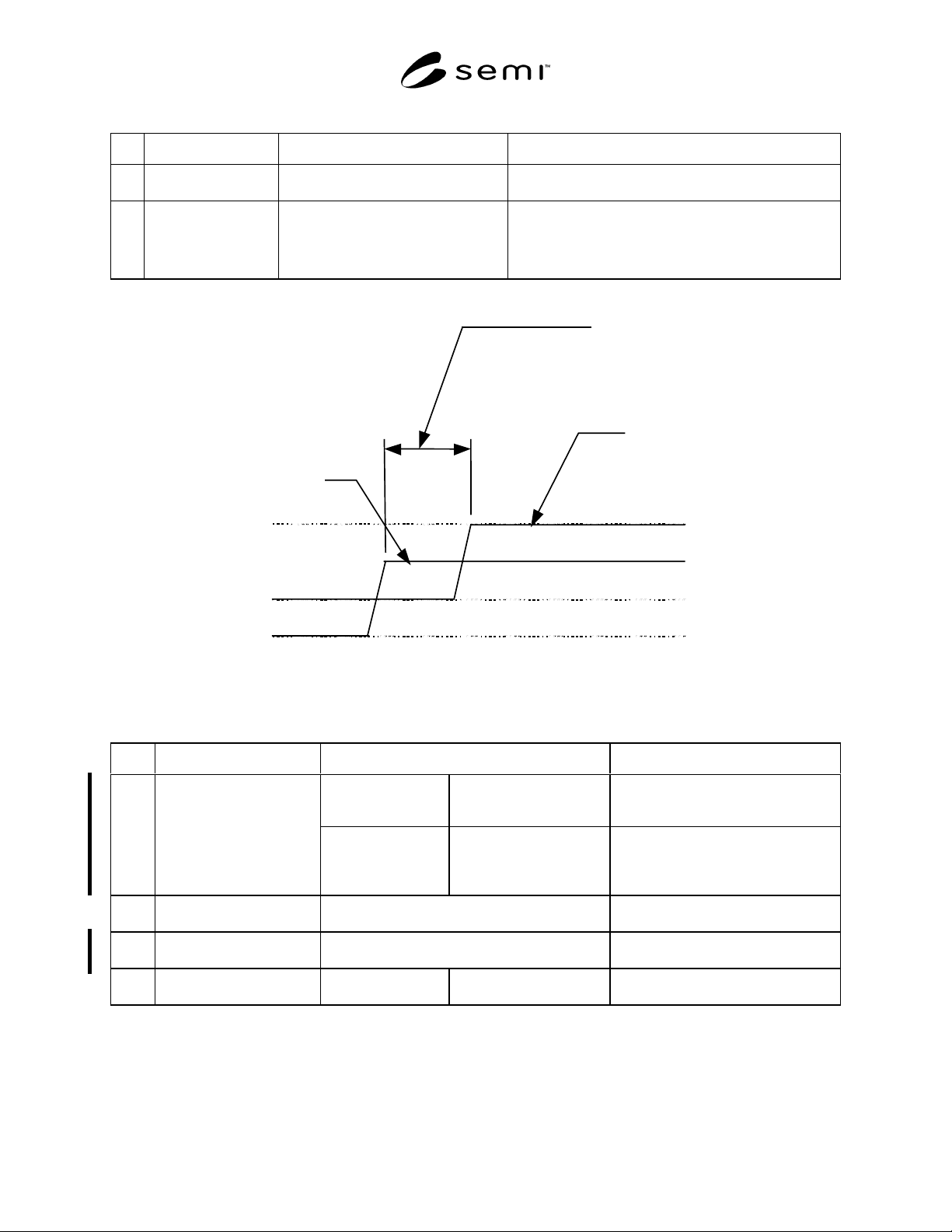
6.2.1.1 Table 2 specifies the required DRP control signals. Table 3 and Figure 2 specify the required response time
for DRP control signals. Table 4 specifies the required power and contacts for DPR control signals. Tables 5 and 6
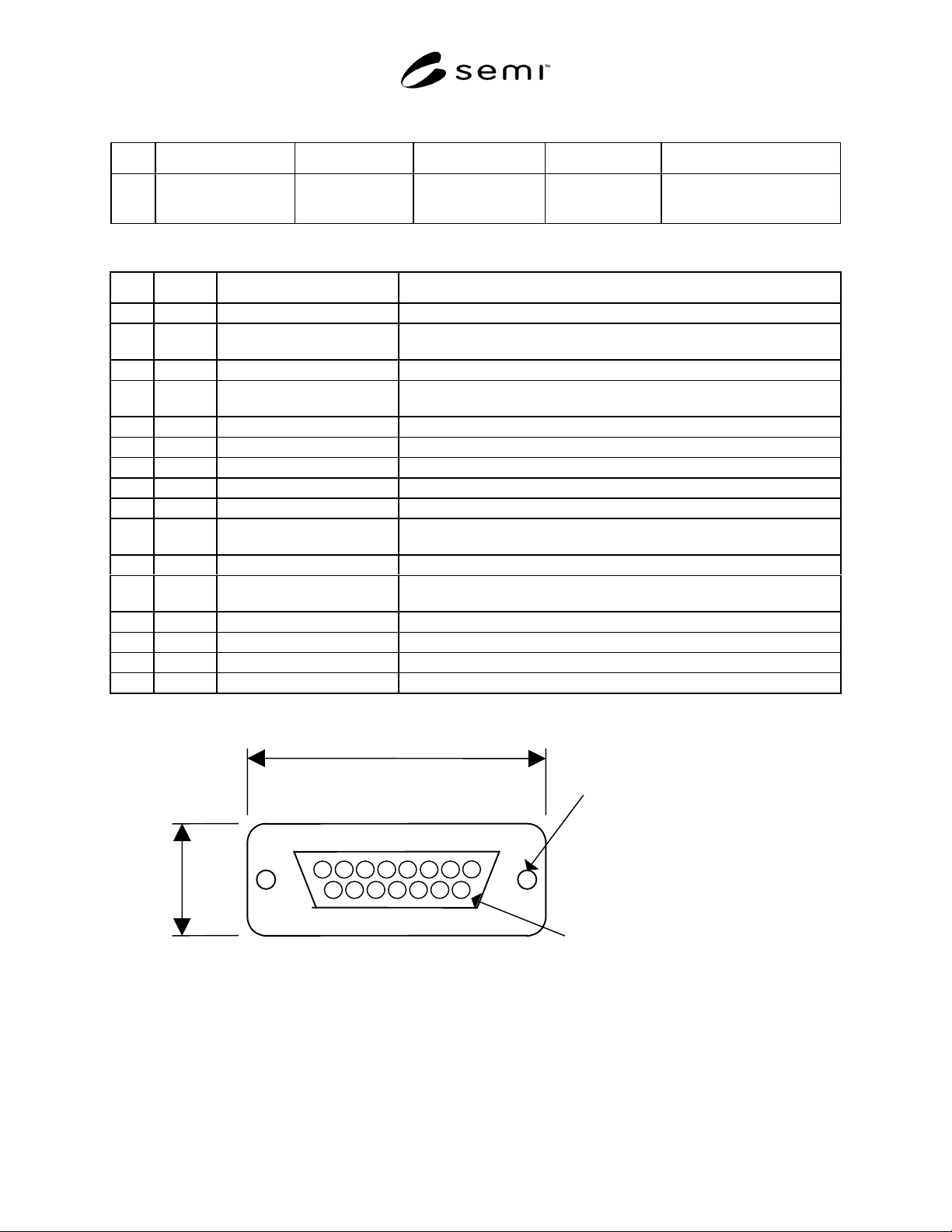
and Figure 3 specify the required connector and pin assignments for DRP control signals.
Table 2 I/O Signals
No. Signal Name Direction Type Remarks
1 Start (Run)/Stop Input signal to Pump Alternate Pump runs when closed
2 Start (Run)/Stop Output signal from Pump Alternate Close on pump start
3 Remote/Local Output signal from Pump Alternate Close during remote
operation
4 Pump Warning Output signal from Pump Alternate Open at warning
5 Pump Alarm Output signal from Pump Alternate Open at alarm
Running status signals
When input power is OFF,
output status signals should
become open (normally
open).
SEMI E73-0301 © SEMI 1998, 20013
Table 3 Response Time for Signals
No. Items Acceptable Response Time Remarks
1 Input Power ON Under 10 seconds
After input power turns on
Objects:
All status signals shall be ready.
2 Control Signals Under 2 seconds
After receiving a signal
See Figure 2
Objects:
a) Start signal (input) ->> Start status (output)
b) Stop signal (input) ->>Stop status (output)
Under 2 seconds
close
open
open
close
Start status
(output)
Supplied: Start/Stop signal
(input)
(Response time for the
control signals)
Figure 2
Example of Response Time for Start Signal and Start Status
Table 4 Signal Power and Contacts
No. Items Power Remarks
Input signals to DRP
(Control signal)
Input signals shall be
driven by the DC power
supply in DRP.
Example: See Figure 4.
a) Photocoupler Input.
b) Relay Input.
1 Signal power supply
Output signals from
DRP (Running status
signal)
Output signals shall be
driven by DC power
supply in tools.
Example: See Figure 5.
a) To photocoupler unit.
b) To relay unit.
c) To TTL unit.
2 Signal power supply
voltage
Signal power supply voltage is between 5 V
DC
and 24 V
DC
3 Acceptable range of signal
power supply voltage
Acceptable voltage range is 4 V
DC
minimum, and
30 V
DC
maximum.
4 Running status signal
contact
Dry contact or open
collector
Acceptable current
100 mA maximum.
SEMI E73-0301 © SEMI 1998, 2001 4
Table 5 Control Signal Connector (pump side)
No. Items Connector Type Referenced Standard Pin Assignments Remarks
1
Control and running
status signals
15 pin
D sub-miniature
Female receptacle
See Table 6 and
Figure 3
See Related Documents for an
example of the specifications
for this connector type.
Table 6 Pin Assignment for Control Signal Connector
No. Pin No. Signal item (polarity) Remarks
1 1 DRP start input ( + )
2 2 (MBP start input) ( + ) An upper pump, such as mechanical booster pump (MBP), to be used with
dry pump systems.
3 3 DRP start/stop status ( + )
4 4 (MBP start/stop status) ( + ) An upper pump, such as mechanical booster pump (MBP), to be used with
dry pump systems.
5 5 Warning status ( + )
6 6 Alarm status ( + )
7 7 Remote/Local status ( + )
88
9 9 DRP start input ( - )
10 10 (MBP start input) ( - ) An upper pump, such as mechanical booster pump (MBP), to be used with
dry pump systems.
11 11 DRP start/stop status ( - )
12 12 (MBP start/stop status) ( - ) An upper pump, such as mechanical booster pump (MBP), to be used with
dry pump systems.
13 13 Warning status ( - )
14 14 Alarm status ( - )
15 15 Remote/Local status ( - )
16 -
MAX. 45.1 mm
MAX. 18.0 mm
Screw lock size : M2.6
Contact pin surface : Au
8
1
9
15
Figure 3
15 pin D Sub-Miniature Female Receptacle