semi合集-English.pdf - 第303页
SEMI E47.1-0305 © SEMI 1997, 2005 18 APPENDIX 1 APPLICATION NOTES NOTICE : The mat erial in this appe ndix is an offici al part of SEMI E47.1 and was appr oved by full letter bal lot procedures on August 27, 2001. A1-1 T…
SEMI E47.1-0305 © SEMI 1997, 2005 17
6.12 FOUP Placement Sensing Pads — The FOUP must have the same carrier sensing pads as is required of the
cassette in SEMI E1.9, including the info pads that communicate information about the carrier such as the carrier
capacity (number of wafers) and type (cassette or FOUP). See SEMI E1.9 for information about info pad
configurations for different wafer carriers similar to FOUPs including front-opening shipping boxes (as defined in
SEMI M31) and single-wafer interface (SWIF) systems (as defined in SEMI E103). Two additional sensing pads
(that can be used continuously while the FOUP is advancing into the FIMS interface) must be located near the center
of the bottom at the same distance from the horizontal datum plane as the carrier sensing pads. In addition, the
surfaces on the door of the FOUP that mate with the seal zones and the reserved spaces for vacuum application may
also be used for door-presence sensing.
7 Related Documents
7.1 SEMI Standards
SEMI E63 — Provisional Mechanical Specification for 300 mm Box Opener/Loader to Tool Standard (BOLTS-M)
Interface
SEMI E103 — Provisional Mechanical Specification for a 300 mm Single-Wafer Box System that Emulates a
FOUP
SEMI M31 — Provisional Mechanical Specification for Front-Opening Shipping Box Used to Transport and Ship
300 mm Wafers
NOTICE: Unless otherwise indicated, all documents cited shall be the latest published versions.
SEMI E47.1-0305 © SEMI 1997, 2005 18
APPENDIX 1
APPLICATION NOTES
NOTICE: The material in this appendix is an official part of SEMI E47.1 and was approved by full letter ballot
procedures on August 27, 2001.
A1-1 The automation handling features do not need to be molded into the plastic shell of the FOUP, but can be
attached as a framework around the shell.
A1-2 To increase the stability of the FOUP on the kinematic couplings, it is recommended that the points on the
FOUP bottom extend as close as practical to the horizontal datum plane to minimize tipping of the FOUP.
A1-3 Skewness, warp, rock, and stiffness are implicitly defined in the geometric tolerances.
A1-4 Dimension y52 is given as a maximum based on the maximum distance to the port door specified in SEMI
E62.
A1-5 The position tolerance of the door of the FOUP is likely to be much larger than the position tolerance of the
registration pins. To make both manual and automated door opening easier, it is recommended that the holes for the
registration pins on the door of the FOUP have openings with a lead-in capability.
NOTE A1-1: If the bottom of the FOUP does not extend below the bottom conveyor rail, the conveyor rail may become
contaminated and may distribute particles.
A1-6 Although both of the retaining features on the bottom of the FOUP must be able to withstand a force in any
direction of f60, continuously applied stress may result in plastic deformation.
A1-7 In order to minimize particle generation when the FOUP door is opened or closed, it is recommended that the
tolerance between the FOUP door and its frame be larger than the tolerance between the FOUP door registration
holes and FIMS registration pins.
A1-8 One type of carrier presence sensor uses a beam of light with an optical detector that is triggered when the
beam of light is attenuated as it passes through the FOUP shell.
A1-9 The use of the registration pins for FOUP door lead-in to the loadport door is not recommended. The
registration pins should be only used to limit the maximum displacement of the FOUP door while on the loadport
door. Neither the FOUP nor FOUP door positions should change as a result of engaging or disengaging the
registration pins. When the Loadport experiences utility loss (such as EMO, vacuum loss, electrical failure, etc.),
the registration pins may be used to maintain the FOUP door’s position, and to ensure that the FOUP door does not
fall off. The clearance between the Registration Pins and the Registration Pin Holes should be less than the
clearance between the outer edge of the FOUP Door and the inner edge of the FOUP Door Frame. Balancing these
tolerances is a FOUP design issue related to the E62 Seal Zone specification. The diameter of the Registration Pin
Holes should be designed to accommodate the Registration Pin tolerance defined in E62 (x31, z31, d31) and the
Registration Pin Hole location tolerance in a FOUP.
A1-10 It is recommended that the FOUP have a capability to roughly position the FOUP door in the FOUP frame
during the door close sequence (during either return of the FOUP door or during latching of the FOUP door). This
positioning capability should keep the clearance between the FOUP frame and the FOUP door larger than sum of the
FOUP (self) tolerance and the E62 registration pin tolerance along with the FOUP door’s circumference. Possible
methods for accomplishing this may include positioning by latch motion and positioning by a slope between the
FOUP frame and the FOUP door.
A1-11 It is recommended that the FOUP have a lead-in mechanism on its latch key holes. This lead-in mechanism
should compensate for the FOUP’s latch key hole location error, as shown in Figure A1-1.
A1-12 It is recommended that the latch key hole mechanisms have some flexibility in their position for compliance
with the latch key positions. The purpose of this is to adjust for any discrepancy in rotation axis between the latch
key and the latch key hole mechanism. As shown in Figure A1-2, if only one side of the latch key pushes on the
inside of the latch key hole, the latch key can not rotate more than half way.
A1-13 It is recommended that the torque required to rotate the FOUP latch key holes be kept small enough that it
will not produce movement of the FOUP door in the x and z directions during latch key rotation.
SEMI E47.1-0305 © SEMI 1997, 2005 19
A1-14 It is recommended that the latch key holes be maintained in the position that unlocks the FOUP door from
the FOUP ( = 0 ± 1° as defined in SEMI E62) while the FOUP is open and in the position that locks the FOUP
door to the FOUP ( = 90 ± 1°) while the FOUP is closed. One method to accomplish this is to have the FOUP
latch key hole mechanisms snap into both end points of their rotation ( = 0 ± 1° and = 90 ± 1°) using a detent
mechanism. The torque required to overcome such a detent mechanism should not exceed f30 (as defined in
SEMI E62).
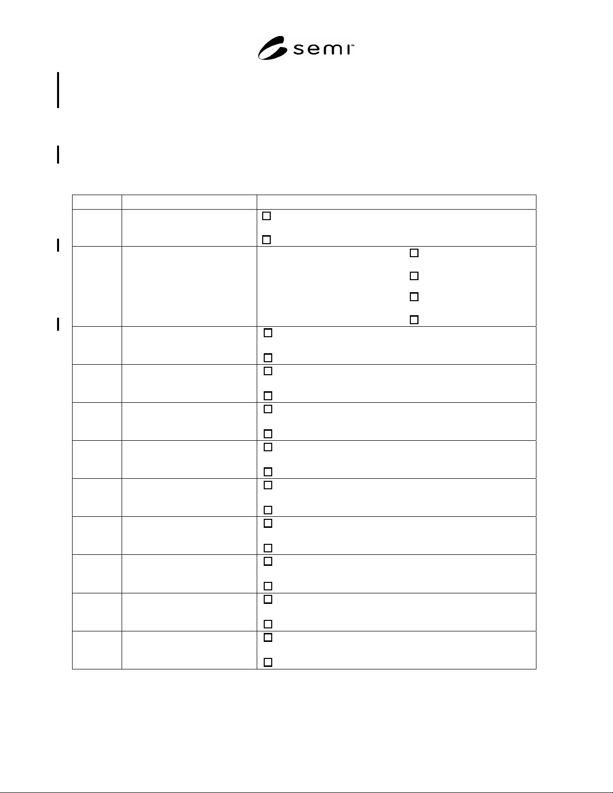
A1-15 Table A1-1 can be used for communicating the compliance of FOUPs to this standard and the options
chosen:
Table A1-1 Optional Features Checklist
Section Optional Feature Choice
4.3 carrier capacity (c)
13 wafers
or
25 wafers
6.1 full 15-mm lead in provided by 3
features that mate with kinematic
coupling pins
Primary kinematic coupling pins
yes
or
no
and
secondary kinematic coupling pins
yes
or
no
6.8 ergonomic manual handles
yes
or
no
6.9 side fork-lift flanges
yes
or
no
6.9 3 kinematic grooves on the top
robotic handling flange
yes
or
no
6.9 rear conveyor rail
yes
or
no
6.9.1 front conveyor surface
yes
or
no
6.12 info pad A height
up (pad missing)
or
down (pad present)
6.12 info pad B height
up (pad missing)
or
down (pad present)
6.12 info pad C height
up (pad missing)
or
down (pad present)
6.12 info pad D height
up (pad missing)
or
down (pad present)