semi合集-English.pdf - 第1969页
SEMI E54.4-0704 © SEMI 1997, 2004 4 5.3.5 input/ output con n ections — connectio ns over a DeviceNet netwo rk that provi de dedicated, special- purpose com munication paths bet ween a pro ducing application an d one or …
SEMI E54.4-0704 © SEMI 1997, 2004 3
4 Referenced Standards
4.1 SEMI Standards
SEMI E30 — Generic Model for Communications and
Control of SEMI Equipment (GEM)
SEMI E39 — Object Services Standard: Concepts,
Behavior, and Services
SEMI E54.1 — Standard for Sensor/Actuator Network
Common Device Model
4.2 ISO Standards
1
ISO 7498 — Basic Reference Model for Open Systems
Interconnection
ISO 11898 — Road Vehicles — Interchange of Digital
Information — Controller Area Network (CAN) for
High-Speed Communications
4.3 Other Documents
DeviceNet Specification — ODVA
2
Controller Area Network Specification — Version 2, R.
Bosch GmbH, + Postfach 50 D-7000, Stuttgart 1,
Germany, 1991
NOTICE: Unless otherwise indicated, all documents
cited shall be the latest published versions.
5 Terminology
Terminology that is common to all of the documents in
this SAN standard may also be defined in the Sensor
Actuator Network Standard. Terminology may be
reproduced here which is defined in other SEMI
documents.
5.1 Abbreviations & Acronyms
5.1.1 CAN — Controller area network
5.1.2 CDM — Common device model
5.1.3 DM — Device manager (object)
5.1.4 DN — DeviceNet
5.1.5 NCS — Network communication standard
5.1.6 OSI — Open systems interconnect
5.1.7 OSS — Object services standard
5.1.8 SAC — Sensor, actuator, controller (object)
5.1.9 SAN — Sensor/actuator network
1 International Organization for Standardization, ISO Central
Secretariat, 1, rue de Varembé, Case postale 56, CH-1211 Geneva 20,
Switzerland. Telephone: 41.22.749.01.11; Fax: 41.22.733.34.30,
Website: www.iso.ch
2 Open DeviceNet Vendor Association, www.odva.org
5.1.10 SDM — Specific device model
5.2 Device Component Definitions — As this standard
defines the presentation or mapping of CDM data
structure and behavior over a network, it makes use of
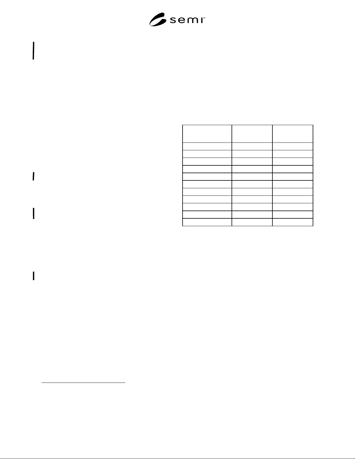
many of the terms in the CDM document. Table 1
provides a mapping of fundamental terminology of the
CDM document into this document and the DeviceNet
specification. Note that Column 2 contains an equal
sign “=” if the definition is used exactly as specified in
the CDM specification.
Table 1 Mapping of CDM to NCS Terminology
CDM Term
NCS Equivalent
DeviceNet
Equivalent
Device = =
Device Model = =
Object =, Class =, Class
Instance = =
Attribute = =
Behavior = =
Service = =
State Diagram = =
Byte = =
Nibble = =
Character String = =
5.3 DeviceNet Specific Definitions
5.3.1 class — a set of objects that all represent the
same kind of system component. A class is a
generalization of an object. All objects in a class are
identical in form and behavior, but may contain
different attribute values.
5.3.2 controller area network (CAN) — a protocol
developed by the Bosch corporation for automotive in-
vehicle networking. The CAN specification specifies
OSI reference model layers 1 and 2, specifically the
physical signaling and media access/data link protocols.
5.3.3 device profile — a DeviceNet specification for a
device that contains an object model for the device
type, the I/O data format for the device type, and the
configuration data and the public interface(s) to that
data.
5.3.4 explicit message connections — connections over
a DeviceNet network that provide generic, multi-
purpose communication paths between two devices.
These connections often are referred to as just
messaging connections. Explicit messages provide the
typical request/response - oriented network communi-
cations.
SEMI E54.4-0704 © SEMI 1997, 2004 4
5.3.5 input/output connections — connections over a
DeviceNet network that provide dedicated, special-
purpose communication paths between a producing
application and one or more consuming applications.
Application-specific I/O data moves through these
ports.
6 Communication Protocol High Level
Structure
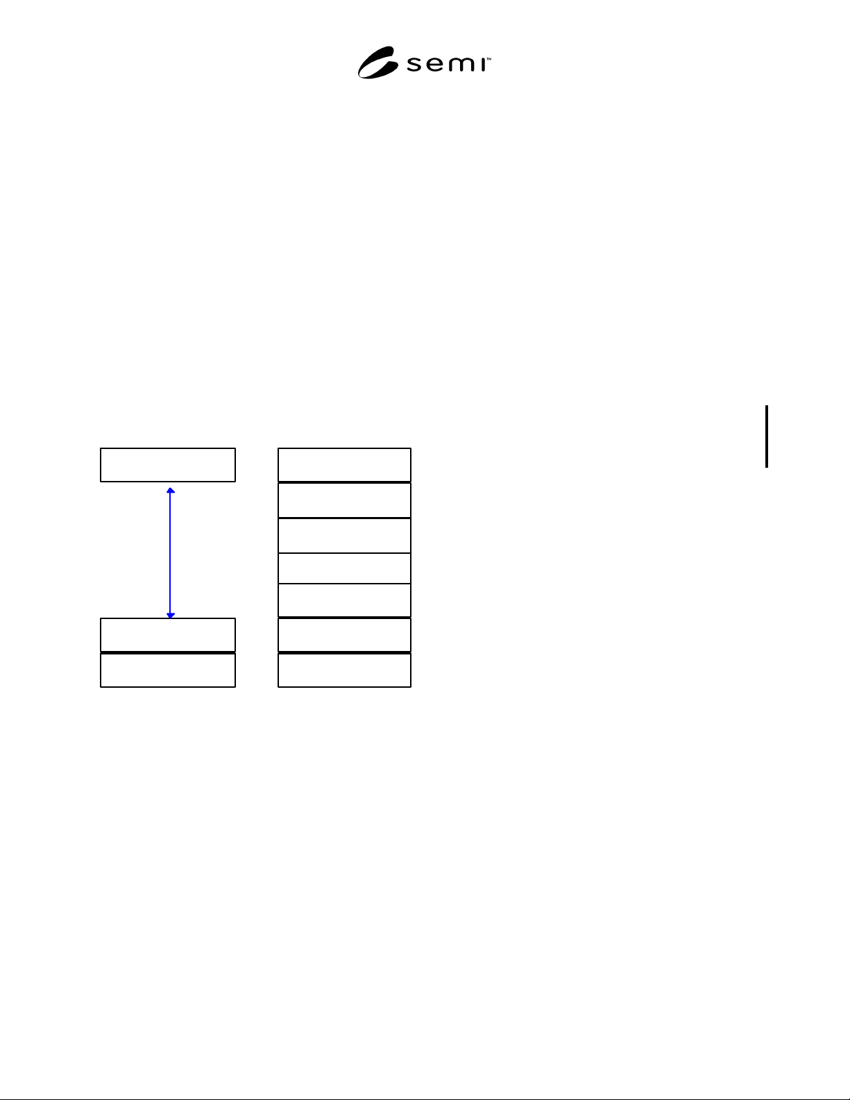
6.1 The DeviceNet protocol is loosely based on a
three-layer architecture. These layers constitute a
collapsed form of the OSI seven-layer architecture,
mapping into the physical, data link, and application
layers of the Reference Model; however, DeviceNet
provides additional functionality (such as connection
support) commonly attributed to other OSI layers. The
high level protocol architecture is shown in Figure 3.
DN Application Layer
CAN Data Link
DN Physical Layer
Layered View of DeviceNet
Application Layer
Presentation Layer
Session Layer
Transport Layer
Network Layer
Data Link Layer
Physical Layer
OSI Reference Model
Figure 3
Layered View of DeviceNet
6.1.1 Note that Figure 3 represents a conceptual view
of the device architecture. Conforming implementations
must implement the services defined in this
specification at each layer and must appear (from the
network) to have implemented this architecture;
however, an internal modular partitioning is not
required. Implementations may sacrifice modularity in
order to achieve high performance.
6.2 The DeviceNet physical layer is fully specified in
Volume 1 of the DN Specification. Features of this
layer include Trunkline - dropline configuration,
simultaneous support for both network-powered and
self-powered devices, and selectable data rates
including at least 125k, 250k, and 500k baud. At the
data link layer, the CAN specification defines a carrier
sense multiple access mechanism for media access
control that avoids collisions and sends frames reliably.
The application layer is specified in Volumes 1 and 2 of
the DN Specification and provides for the definition of
DeviceNet applications as a collection of addressable
objects. Two basic categories of objects exist:
Communication Objects and Application Objects.
Communication Objects manage and provide for the
runtime exchange of messages across DeviceNet.
Application Objects implement product-specific
features and/or provide a logical interface to product-
specific information of devices on a DeviceNet
network.
6.3 In the remainder of this section, the protocol
structure is described in more detail in terms of the OSI
seven layer reference model, the object model
environment, and network management specifications.
6.4 Physical Layer — The device shall comply with the
DeviceNet physical layer specification as well as the
" Interface Guidelines for DeviceNet Devices on
Semiconductor Manufacturing Tools" which is
published as part of the DeviceNet specification. This
includes physical signaling (levels and baud rates -
detailed in the CAN specification), transceivers, node
isolation, media topology, cable specifications, network
connectors and taps, and power considerations (load
limits, system tolerances, and power supply options).
6.4.1 Physical Layer Enhancements — This standard
supports the following physical layer enhancement to
the DeviceNet specifications:
• The transmission media, including both trunk cable
and drop cable, shall be DeviceNet Thin Cable.
Specifications on this cable and its utilization in
DeviceNet systems (e.g., maximum trunk and drop
lengths) are included in the DeviceNet
specification.
6.5 Data Link Layer — The device shall comply with
the DeviceNet Data Link Layer Specifications (i.e.,
Controller Area Network Specification: Version 2).
This includes the media access control mechanism and
the logical link control mechanism. Addressing is
currently limited to 11 bits.
6.6 Network Layer — There is no distinct network
layer.
6.7 Transport Layer — There is no distinct transport
layer. Some of the functionality of this layer is
implemented in the Application Layer. Specific
functions include: segmentation/reassembly for full
message delivery and the establishment of node-to-node
connections.
6.8 Session Layer — There is no distinct session layer.

SEMI E54.4-0704 © SEMI 1997, 2004 5
6.9 Presentation Layer — There is no distinct
presentation layer. Data types and data presentation in
DeviceNet messages are specified as part of the
DeviceNet object definitions and object attribute and
service communication protocol.
6.10 Application Layer — The device shall comply
with the DeviceNet application layer specification for
defining and addressing objects, including their
attributes and services, and enabling specified network
behavior. The device shall comply with the object
model specifications provided in the DeviceNet
specification as well as the “Interface Guidelines for
DeviceNet Devices on Semiconductor Manufacturing
Tools” component of the DeviceNet specification. In
addition, the device shall comply with the object
specifications defined in Section 7 of this document.
6.10.1 Object Models — The DeviceNet protocol
provides an object-oriented specification for creating,
defining, and addressing objects explicitly, including
their attributes and services (i.e., explicit messaging),
and creating, defining, and communicating object
attribute assemblies in an application-dependent format
(i.e., input/output messaging). The device shall comply
with the object model specifications provided in the
DeviceNet documentation. In addition, the device shall
comply with the object specifications defined in Section
7 of this document.
6.11 Network Management — The device shall comply
with the DeviceNet network management specifications
(e.g., physical layer bit rate, duplicate MAC ID
detection, master-slave, and peer-to-peer network
management). No (additional) network management
functions are specified in this document.
7 Required Object Types
7.1 The DeviceNet specification identifies and
describes objects (i.e., classes) that must exist in all
DeviceNet-compliant devices. The Common Device
Model specification additionally identifies two objects
(namely the Device Manager (DM) and Sensor
Actuator Controller (SAC) objects) that must exist in all
SEMI-compliant SAN devices. The required object
types for a SEMI-compliant SAN device, using the
network communication specification described herein,
necessarily comprise the union of the above to
requirements.
7.2 A list of required and optional object types is given
in Table 2. Note that the Sensor, Actuator, and
Controller object types are not required and are
indicated as optional in the CDM specification. These
objects are aggregated together to form a SEMI- and
DN- compliant device, as shown in Figure 4.
7.3 The mapping of the DM and SAC objects are
combined into a single object in DeviceNet called the
S-Device Supervisor (DS) object.