semi合集-English.pdf - 第4581页
SEMI D33-0703 © SEMI 2003 3 Figure 3b 13 m easuring poi nts Figure 3a 25 m easuring poi nts Figure 3c 9 m easuring poi nts Figure 3d 5 m easuring poi nts 6.3.4 Color 6.3.4.1 In this standa rd, color coordinate sy stems a…
SEMI D33-0703 © SEMI 2003 2
6.2.3 Measuring Equipment
6.2.3.1 Instrument for Driving of BLU
6.2.3.1.1 In this standard a DC power supply is needed
and an inverter for BLU driving of electro-optical test.
It is required that the DC-power supply has the range of
the output voltage between 0 to 30V and has the range
of the output current between 0 to 8A.
6.2.3.2 Instrument For Optical Measurement
6.2.3.2.1 In this standard, spectroradiometer is needed
for optical test. Spectroradiometer is more adequate
than a filter photometer for BLU color measurement
and it can use filter photometer and spectroradiometer
for luminance measurement.
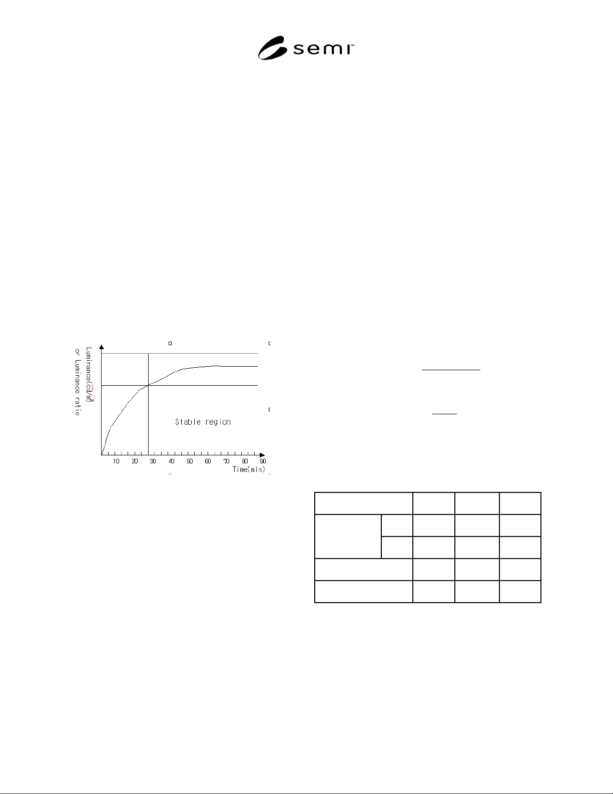
6.2.4 Warm-Up Time
6.2.4.1 Warm-up time is the period from power-on to
saturation of the light intensity. The optical
measurement needs 15 to 30 minutes for a more
accurate measurement in case of luminance and
luminance uniformity.
Figure 2
The Warm-Up Time of BLU
6.2.5 Others
6.2.5.1 It is recommended that the user record the
environment and condition such as: temperature,
humidity, illumination of surrounding, testing distance,
warm-up time, lamp current, etc.
6.3 Measurement Items
6.3.1 The following measurement items are
recommended for BLU, but these items depend on user
requirements if they are specified.
6.3.2 Luminance
6.3.2.1 It is the surface luminance that is detected in all
test areas. Luminance should be expressed in a unit
such as candelas per meter squared [cd/m
2
]. This
luminance is the value measured at one center point or
average value at several testing points. Generally, the
lamp current of BLU should be set to typical lamp
current. If the lamp current value has fluctuation state,
the user should wait by stable state. The measurements
are performed in the dark room under standard
measuring conditions and design viewing direction.
6.3.3 Luminance Uniformity
6.3.3.1 Luminance uniformity is a measure of how well
the luminance remains constant over the surface of the
active area and it is a closely related measurement to
luminance itself. Backlights are particularly liable to
have the non-uniformity characteristics. The measuring
method is similar to the luminance measuring method.
In this measurement, it is important to determine the
testing position. The determination of the testing
position occur some different testing result. In this
standard, we calculate the uniformity with the ratio of
max luminance and min luminance level. The simple
formulas are below. There are two formulas for
uniformity. These formulas explain the non-uniformity
concept, but they very popular with related industry.
Measuring position in luminance uniformity formula:
100)((%)
max
minmax
×
−
=
L
LL
Uniformity
L
L
ratioUniformity
min
max
)( =
NOTE 1: For example, if the maximum luminance is
100 cd/m
2
and the minimum luminance is 80 cd/m
2
the
Uniformity (%) is 20%. And the uniformity (ratio) is 1.25.
Comparison Case A Case B Case C
Max. 200 200 200
Luminance
Min. 140 160 180
Uniformity (%) 30% 20% 10%
Uniformity (ratio) 1.43 1.25 1.11
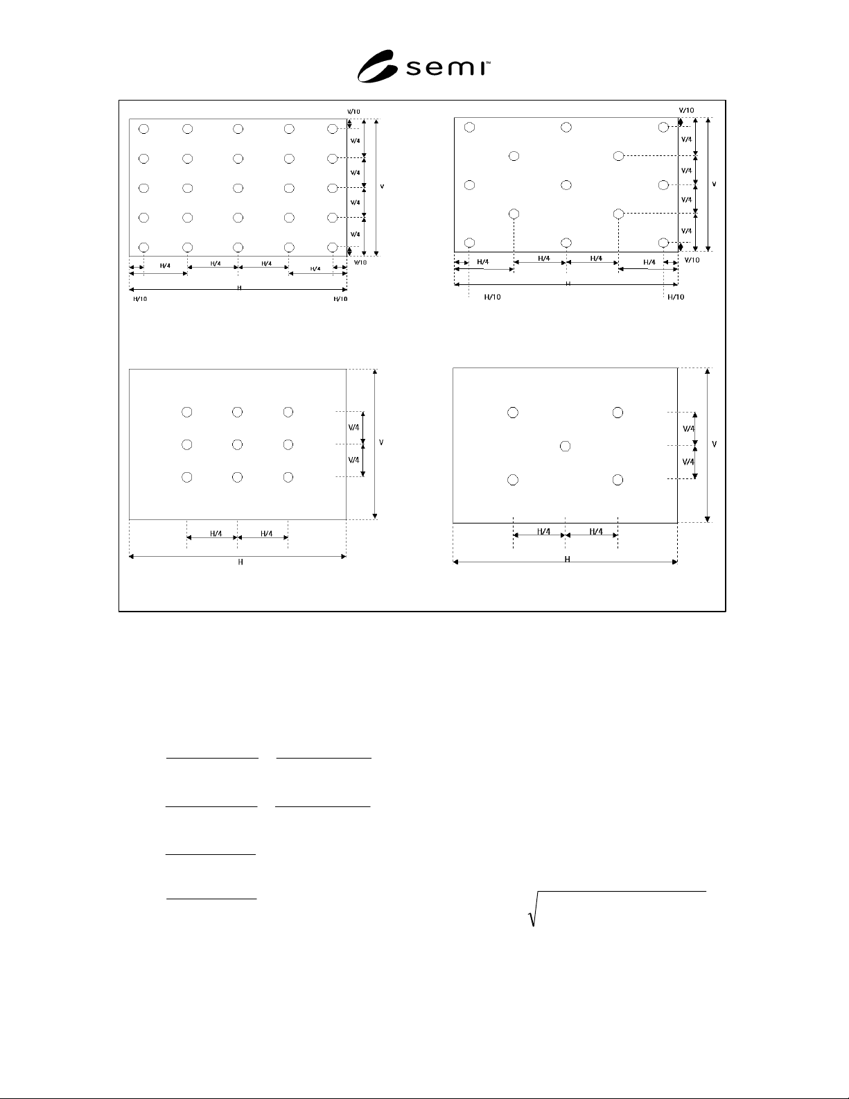
6.3.3.2 For this calculation, there are some positioning
methods and the each user can select the test point
option (the testing number is 5/9/13/25 point).
6.3.3.3 Figures 3a to 3d show each test position and
test number.
SEMI D33-0703 © SEMI 2003 3
Figure 3b
13 measuring points
Figure 3a
25 measuring points
Figure 3c
9 measuring points
Figure 3d
5 measuring points
6.3.4 Color
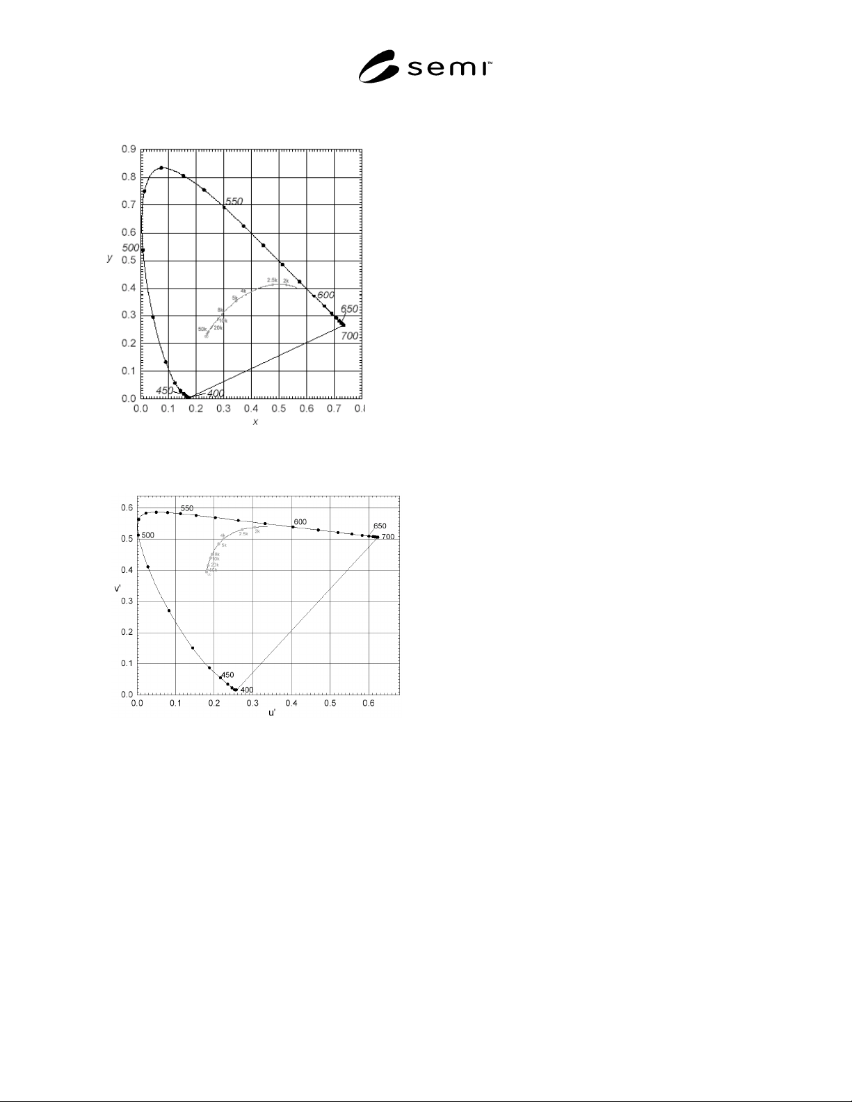
6.3.4.1 In this standard, color coordinate systems are
the 1931 or 1976 CIE systems. CIE1931 use the ‘x’ and
‘y’ coordination and CIE1976 use u’ and v’
coordination. The relation between CIE1931 to
CIE1976 is below:
36'48'18
'12
36'48'18
'27
3122
9
315
9
'
3122
4
315
4
'
+−
=
+−
=
++−
=
++
=
++−
=
++
=
vu
v
y
vu
u
x
yx
y
ZYX
Y
v
yx
x
ZYX
X
u
6.3.4.2 Generally, because the light source of BLU is a
discontinue wavelength, color should be measured by
spectroradiometer. It is more accurate than filter
colorimeter for color measuring. In this standard, the
measuring distance and viewing direction are the same
with the luminance testing method.
6.3.5 Color Uniformity
6.3.5.1 Color Uniformity is a same meaning with the
Color difference in this standard. It means how the
displays have the consistent chromaticity. In case of the
color uniformity, we use the u’ and v’ coordinates from
CIE1976. The reference point is center position. It is
referenced the ∆u’v’ formula.
The formula is below:
)()(
'
2
'
1
'
2
'
1
''
22
vvuu
vu
−−
+=∆
6.3.5.2 There are some positioning methods for color
uniformity test. It is the same point with luminance
SEMI D33-0703 © SEMI 2003 4
uniformity, but in this standard, five point color
uniformity is recommended. (Confer with Figure 3d.)
Figure 4
The 1931 CIE Coordinates (x,y)
Figure 5
The 1976 CIE Coordinates (u’,v’)
NOTICE: SEMI makes no warranties or
representations as to the suitability of the standards set
forth herein for any particular application. The
determination of the suitability of the standard is solely
the responsibility of the user. Users are cautioned to
refer to manufacturer's instructions, product labels,
product data sheets, and other relevant literature,
respecting any materials or equipment mentioned
herein. These standards are subject to change without
notice.
By publication of this standard, Semiconductor
Equipment and Materials International (SEMI) takes no
position respecting the validity of any patent rights or
copyrights asserted in connection with any items
mentioned in this standard. Users of this standard are
expressly advised that determination of any such patent
rights or copyrights, and the risk of infringement of
such rights are entirely their own responsibility.
Copyright by SEMI® (Semiconductor Equipment and Materials
International), 3081 Zanker Road, San Jose, CA 95134. Reproduction o
f
the contents in whole or in part is forbidden without express written
consent of SEMI.