semi合集-English.pdf - 第86页
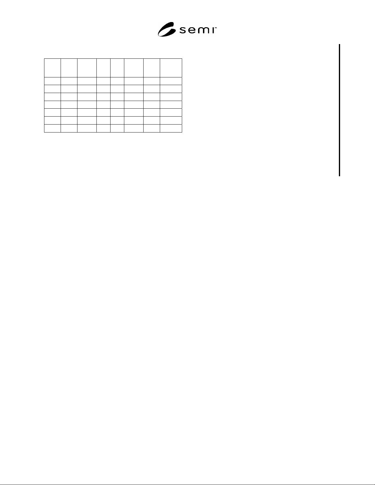
SEMI E7-91 © SEMI 1984, 2004 3 Table 1 Flexible Cord and Cable Conduc tor Color Code No. Phases No. Wires Voltage ØA BØ CØ N Grd 1 2 #3 120 Blk Wht #1 1 2 #3 208 Blk Red 1 3 120 Blk Wht #1 Green #2 1 3 208 Blk Red Green …
SEMI E7-91 © SEMI 1984, 2004 2
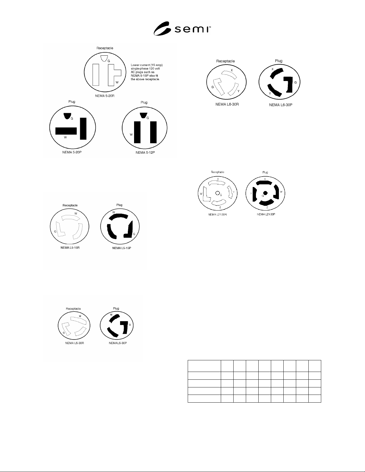
Figure 1
Dead front plugs are preferred.
6.1.2 120 Volt, Ø, 30 AMPs max., locking type.
Figure 2
6.1.3 120 Volt, 1Ø, 30 AMPs max., locking blade type.
Figure 3
6.1.4 250 Volt, 1Ø, 30 AMPs max., locking type
Figure 4
6.1.5 120/208 Volt, 3ØY, 30 AMPs max., locking type
(4 pole, 5-wire grounding)
Figure 5
6.1.6 Above 10,000 watts, use of connectors is
discouraged. Wherever possible, such loads should be
wired into junction boxes using appropriate crimped or
pressure terminations.
7 Cordage and Cables
7.1 The flexible cord and cable types shown are
examples; for more detail see the National Electrical
Code.
7.2 The following table gives the allowable ampacity
for the specified number of current-carrying copper
conductors in a cord.
7.3 Type SO-ST-STO preferred with 600 Volt
insulation.
AWG #18 #16 #14 #12 #10 #8 #6 #4
2 cond. 10 13 18 25 30 40 55 70
3 cond. 7 10 15 20 25 35 45 60
4 cond. 5.6 8 12 16 20 28 36 48
5 cond. 5.6 8 12 16 20 28 36 48
SEMI E7-91 © SEMI 1984, 2004 3
Table 1 Flexible Cord and Cable Conductor Color
Code
No.
Phases
No.
Wires
Voltage ØA BØ CØ N Grd
1 2
#3
120 Blk Wht
#1
1 2
#3
208 Blk Red
1 3 120 Blk Wht
#1
Green
#2
1 3 208 Blk Red Green
#2
1 4 208/480 Blk Red Wht
#1
Green
#2
3 4 208/480 Blk Red Orange Green
#2
3 5 208/480 Blk Red Orange Wht
#1
Green
#2
#1: Natural Grey or Light Blue may be used. Under no circumstances
may White, Natural Grey or Light Blue be used for any purpose other
than to identify neutral or rounded conductors.
#2: Green/Yellow may be used. Green/Yellow willbe Green with one
or more Yellow stripes (Green = 50 to 70%; Yellow = 50 to 30%).
Green/Yellow is the only color internationally accepted for use as an
equipment grounding conductor. Under no circumstances may
Green/Yellow, Green or Yellow be used for any purpose other than to
identify grounding conductors.
#3: For double insulated machines only.
8 Related Documents
8.1 The following are sources of further information
concerning electrical interfaces:
Electrical Industries Association (EIA), 2001 I Street,
N.W., Washington, DC 20006
Joint Industrial Council (JlC), 7901 Westpark Dr.,
McLean, VA 22101
Western Electric Co., Inc. (WECO), “Standards for
Electrical Design and Construction,” Drawing #C-
284805, Machine Design Dept., Allentown Works,
Allentown, PA 18103
Occupational Safety & Health Administration,
Standards (OSHA) Part 1910, Title 29, Code of Federal
Regulations, Dated 7 Nov. 1978, Dept. of Labor,
Washington, DC
Underwriter’s Laboratories, Inc. (UL), 207 E. Ohio St.,
Chicago, IL 60611
IBM Corporate Bulletin, “Nonproduct Equipment
Design Standard,” “CB 3-0502-202 Support Equipment
Standard,” 1983-05, or succession thereto
American National Standards Institute, C73.73,
American National Standards Institute, 1430 Broadway,
New York, NY 10018
NOTICE: SEMI makes no warranties or
representations as to the suitability of the standards set
forth herein for any particular application. The
determination of the suitability of the standard is solely
the responsibility of the user. Users are cautioned to
refer to manufacturer's instructions, product labels,
product data sheets, and other relevant literature,
respecting any materials or equipment mentioned
herein. These standards are subject to change without
notice.
By publication of this standard, Semiconductor
Equipment and Materials International (SEMI) takes no
position respecting the validity of any patent rights or
copyrights asserted in connection with any items
mentioned in this standard. Users of this standard are
expressly advised that determination of any such patent
rights or copyrights, and the risk of infringement of
such rights are entirely their own responsibility.
Copyright by SEMI® (Semiconductor Equipment and Materials
International), 3081 Zanker Road, San Jose, CA 95134. Reproduction of
the contents in whole or in part is forbidden without express written
consent of SEMI.

SEMI E10-0304
E
© SEMI 1986, 2004 1
SEMI E10-0304
E
SPECIFICATION FOR DEFINITION AND MEASUREMENT OF
EQUIPMENT RELIABILITY, AVAILABILITY, AND MAINTAINABILITY
(RAM)
This specification was technically approved by the Global Metrics Committee and is the direct responsibility
of the North American Metrics Committee. Current edition approved by the North American Regional
Standards Committee on October 15, 2003. Initially available at www.semi.org February 2004; to be
published March 2004. Originally published in 1986; previously published July 2001.
E
This standard was editorially modified in February 2004 to include changes omitted from the previous
edition. Changes were made to Table 1, Table R1-3, and Section R1-7.
1 Purpose
1.1 This document establishes a common basis for
communication between users and suppliers of
semiconductor manufacturing equipment by providing
standards for measuring RAM performance of that
equipment in a manufacturing environment.
2 Scope
2.1 The document defines six basic equipment states
into which all equipment conditions and periods of time
must fall. The equipment states are determined by
functional issues, independent of who performs the
function. The measurement of equipment reliability in
this specification concentrates on the relationship of
equipment failures to equipment usage, rather than the
relationship of failures to total elapsed time.
2.2 Section 5 (Equipment States) defines how
equipment time is categorized. Section 6 (RAM
Measurement) defines formulas for measurement of
equipment performance. Section 7 (Uncertainty
Measurement) gives additional methods for evaluating
the statistical significance of calculated performance
metrics.
2.3 Effective application of this specification requires
that equipment performance (RAM) be tracked with
regard to time and/or equipment cycles. Automated
tracking of equipment states is not within the scope of
this specification, but is covered by SEMI E58. Clear
and effective communication among users and suppliers
promotes continuous improvement in equipment
performance.
2.4 The RAM indices in this specification may be
applied directly to non-cluster tools at the whole
equipment and sub-system levels. The RAM indices
may be applied at the sub-system level (e.g., process
module) for multi-path cluster tools.
NOTICE: This standard does not purport to address
safety issues, if any, associated with its use. It is the
responsibility of the users of this standard to establish
appropriate safety and health practices and determine
the applicability of regulatory or other limitations prior
to use.
3 Referenced Standards
3.1 SEMI Standards
SEMI E58 — Automated Reliability, Availability, and
Maintainability Standard (ARAMS)
NOTICE: Unless otherwise indicated, all documents
cited shall be the latest published versions.
4 Terminology
4.1 Definitions
4.1.1 availability — the probability that the equipment
will be in a condition to perform its intended function
when required.
4.1.2 cluster tool — a manufacturing system made up
of integrated processing modules mechanically linked
together (the modules may or may not come from the
same supplier).
4.1.2.1 single path cluster tool — a cluster tool with
only one process flow path (as used).
4.1.2.2 multi-path cluster tool — a cluster tool with
more than one independent process flow path (e.g.,
multiple load ports/load-locks, multiple process
chambers of the same type) and used as such.
4.1.3 cycle — one complete operational sequence
(including unit load and unload) of processing,
manufacturing, or testing steps for an equipment system
or subsystem. In single unit processing systems, the
number of cycles equals the number of units processed.
In batch systems, the number of cycles equals the
number of batches processed.
4.1.4 downtime (DT) — the time when the equipment is
not in a condition, or is not available, to perform its
intended function. It does not include any portion of
non-scheduled time.