semi合集-English.pdf - 第4105页
SEMI F60-0301 © SEMI 2001 1 SEMI F60-0301 TEST METHOD FOR ESCA EV A LU ATION OF SURFA CE COMPOSITION OF WETTED SURFA C ES OF PA SSIV ATED 316L STA I NLESS STEEL COMPONENTS This test method was tec hnically approved by th…
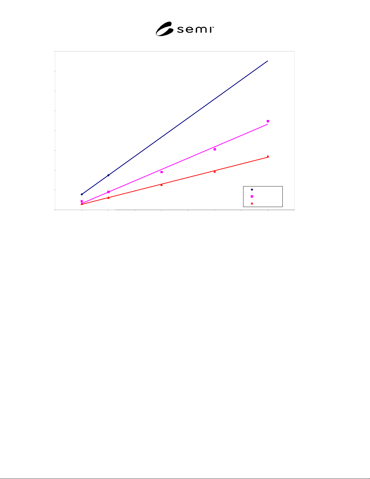
SEMI F59-0302 © SEMI 2000, 2002 10
Normal Flow Rate
Differential Pressure
Test Pressure 1
Test Pressure 2
Test Pressure 3
Figure 4
Example of a Flow Pressure Drop Curve for a Filter
NOTICE: SEMI makes no warranties or representations as to the suitability of the standard set forth herein for any
particular application. The determination of the suitability of the standard is solely the responsibility of the user.
Users are cautioned to refer to manufacturer’s instructions, product labels, product data sheets, and other relevant
literature respecting any materials mentioned herein. These standards are subject to change without notice.
The user’s attention is called to the possibility that compliance with this standard may require use of copy-righted
material or of an invention covered by patent rights. By publication of this standard, SEMI takes no position
respecting the validity of any patent rights or copyrights asserted in connection with any item mentioned in this
standard. Users of this standard are expressly advised that determination of any such patent rights or copyrights, and
the risk of infringement of such rights, are entirely their own responsibility.
Copyright by SEMI® (Semiconductor Equipment and Materials
International), 3081 Zanker Road, San Jose, CA 95134. Reproduction o
f
the contents in whole or in part is forbidden without express writte
n
consent of SEMI.

SEMI F60-0301 © SEMI 20011
SEMI F60-0301
TEST METHOD FOR ESCA EVALUATION OF SURFACE
COMPOSITION OF WETTED SURFACES OF PASSIVATED 316L
STAINLESS STEEL COMPONENTS
This test method was technically approved by the Global Facilities Committee and is the direct responsibility
of the North American Facilities Committee. Current edition approved by the North American Regional
Standards Committee on November 22, 2000. Initially available at www.semi.org December 2000; to be
published March 2001.
1 Purpose
1.1 The purpose of this document is to define a
method for testing passivated 316L stainless steel
components being considered for installation into a
high-purity gas distribution system. Application of this
test method is expected to yield comparable results
among components tested for the purposes of
qualification for this installation.
1.2 This document defines a method of testing the
interior surfaces of stainless steel tubing, fittings,
valves, and other components to determine the surface
composition and chemistry, as a measure of the
effectiveness of passivation processes.
1.3 The objective of this method is to describe a
general set of instrument parameters and conditions that
will achieve precise and reproducible measurements of
important surface chemistry within the chromium-
enriched oxide layer.
2 Scope
2.1 This document describes a test method to
characterize “as received” surface composition and
chemistry encompassing all chromium-enriched
stainless steel surfaces in tubing, fittings, valves, and
other components. This procedure involves
measurement of total Cr/Fe ratios, Cr
ox
/Fe
ox
oxide
species ratios, and the surface elemental compositions
by Electron Spectroscopy for Chemical Analysis
(ESCA), also called X-ray Photoelectron Spectroscopy
(XPS).
2.2 This document also describes the test method for a
compositional ESCA depth profile measurement for Cr,
Fe, Ni, O and C from the as-received surface, through
the oxide layers, and extending into the base metal.
The depth profile measurement evaluates the oxide
thickness and the relative composition throughout the
modified surface layer as a result of the passivation
process.
2.3 This standard does not purport to address safety
issues, if any, associated with its use. It is the
responsibility of the users of this standard to establish
appropriate safety health practices and determine the
applicability or regulatory limitations prior to use.
3 Limitations
3.1 This test method is intended to be used by ESCA
analysts familiar with the instrumentation and
technique. The ESCA instrument must be calibrated
and maintained to pertinent manufacturer’s
specifications. The method is not intended to preclude
the use of any particular brand or model of surface
analysis equipment. While most of the test
methodology has been developed using specific
instrumentation, this method can be adapted to most
surface analytical instrumentation.
3.2 The effects of the depth of analysis of the
technique and surface contamination affect the results
of this test method. These are discussed in the attached
appendix. Surface roughness, non-planarity of the
surface, and differential sputtering rates for the different
chemical species also cause measurement uncertainties
in this test method
4 Referenced Standards
NOTE 1: As listed or revised, all documents cited shall be the
latest publications of adopted standards.
4.1 SEMI Standards
SEMI F19 — Specification for the Finish of the Wetted
Surfaces of Electropolished 316L Stainless Steel
Components.
4.2 ASTM Standards
1
A276 — Standard Specification for Stainless Steel Bars
and Shapes.
A751 — Standard Test Methods, Practices, and
Terminology for Chemical Analysis of Steel Products.
E673 — Standard Terminology Relating to Surface
Analysis.
E902 — Standard Practice for Checking the Operating
Characteristics of X-ray Photoelectron Spectrometers.
1 American Society for Testing and Materials, 1916 Race Street,
Philadelphia, PA 19103

SEMI F60-0301 © SEMI 2001 2
E1078 — Standard Guide for Specimen Handling in
Auger Electron Spectroscopy and X-ray Photoelectron
Spectroscopy.
4.3 NIST Standard
2
SRD20 — NIST X-ray Photoelectron Spectroscopy
Database.
4.4 Physical Electronics
3
Moulder, et al. — Handbook of X-ray Photoelectron
Spectroscopy.
5 Terminology
5.1 Acronyms and Abbreviations
5.1.1 ESCA — Electron Spectroscopy for Chemical
Analysis.
5.1.2 XPS — X-ray Photoelectron Spectroscopy, an
equivalent name for ESCA.
5.2 Definitions
5.2.1 sampling volume — the volume from which
photoelectrons are detected. The x-ray spot size and/or
the lens and aperture system of the electron analyzer
determine lateral dimensions. A length of three times
the photoelectron mean free path is considered the
maximum depth sensitivity. Sampling volume is
dependent on the sample material and TOA. The
acceptance angle of the analyzer will also influence the
distribution of the depth information.
5.2.2 take-off angle (TOA) — the angle that the
collection lens forms with the sample plane.
6 Summary of Method
6.1 Data Acquisition
6.1.1 Acquire elemental survey and calculate
elemental composition of “as received” wetted surface.
6.1.2 Acquire chromium and iron regions at high
resolution. Calculate total Cr/Fe ratio and Cr oxide/Fe
oxide ratios from these regions.
6.1.3 Acquire a compositional depth profile to
determine the relative abundance of C, O, Cr, Fe and
Ni. Additional elements may be included as desired
(i.e., molybdenum, silicon and nitrogen). If minor
elements are included in the profile the instrument
parameters should be chosen to allow for a detection
limit of 1 atomic percent (at%) or better.
6.2 Reporting — Data is provided consisting of:
2 National Institute of Standards and Technology, Gaithersburg, MD
20899
3 Physical Electronics, Eden Prairie, MN 55344
6.2.1 A survey spectrum extending from at least 0-
1100eV.
6.2.2 The high-resolution Cr (2p
3/2
) and Fe (2p
3/2
)
spectra from the as-received surface.
6.2.3 A compositional depth profile plot including C,
O, Cr, Fe and Ni as a function of sputtering time.
7 Possible Interferences
7.1 Mo (3d) and S (2s) — use S (2p) for quantification
of sulfur. Molybdenum will appear as a doublet;
quantity may be overestimated.
7.2 Fe (2p
3/2
) and Ni Auger — ignore.
7.3 Mo (3p) and N (1s) — the ability to accurately
quantify the nitrogen will depend upon the chemical
state of both the nitrogen and molybdenum. In some
cases the nitrogen will be overestimated from a survey
scan quantification.
8 Apparatus
8.1 Instrumentation — Any ESCA instrument with
definable area of analysis approximately 1 mm or less
and sufficient count rate to provide detection of low
level contaminants at one atomic percent or greater. A
count rate of at least 100,000 counts per minute for
clean Au (4f
7/2
) should indicate sufficient sensitivity.
8.2 The instrument should have peak resolution of 1
eV FWHM Au (4f
7/2
) or better (i.e., < 1 eV) to ensure
species separation of metallic and oxide forms of
chromium and iron.
8.3 If the instrument is of a variable take-off angle
(TOA) design, the geometry should be set to a TOA of
approximately 35
o
. Instruments with geometries
significantly different from this, or with magnetic
electron collection lens may provide analysis from a
different sampling volume. The angle of the incident
X-ray irradiation with respect to the sample plane and
TOA must be recorded.
8.4 Data reduction software must have the ability to
select an iterated Shirley-curve background.
9 Reagents and Materials
9.1 Instrument Calibration Materials — Refer to
instrument manufacturer recommendations or ASTM
E902. A measurement of the binding energy difference
between the Au (4f
7/2
) at 84.0 eV and Cu (2p
3/2
) at
932.6 eV is an acceptable method of calibrating
analyzer linearity. A value of ± 3σ based upon a
minimum of 10 historical measurements of less than ±
0.25 eV is acceptable.