semi合集-English.pdf - 第3507页
SEMI E134-0305 © SEMI 2004, 2005 60 16 Requirements for Compliance 16.1 Table 88 provides a checklist for Data Collection Mana gement compliance. Note that the DCP State Models described in Se ction 12 are internal t o t…

SEMI E134-0305 © SEMI 2004, 2005 59
15.2.6.2 DCPDeactivation — The equipment shall send this notification to a consumer whenever one or more
DCPs that were activated by that consumer have been deactivated. Note that the consumer should make no
assumption regarding the timing of the receipt of this notification and the receipt of the last transmitted data for any
deactivated DCPs provided in the notification. The consumer may receive one or more data collection reports from
the named DCPs after receiving this notification.
15.2.6.2.1 DCPDeactivation Operation Arguments
Table 85 DCPDeactivation Argument Definitions
Argument Description Kind Form
deactivationNotice Information describing the DCPs that
have been deactivated.
in List of one or more structured data elements, each
of type DCPDeactivated, described in Section
9.1.2.7.6.
15.2.6.3 DCPHibernation — The equipment shall send this notification to a consumer whenever one or more DCPs
that were activated by that consumer are going into the hibernating state. Note that the consumer should make no
assumption regarding the timing of the receipt of this notification and the receipt of the last transmitted data for any
deactivated DCPs provided in the notification. The consumer may receive one or more data collection reports from
the named DCPs after receiving this notification.
15.2.6.3.1 DCPHibernation Operation Arguments
Table 86 DCPHibernation Argument Definitions
Argument Description Kind Form
hibernatingPlans Information describing the DCPs that are
going into hibernation.
in List of one or more structured data elements, each
of type DCPHibernated, described in Section
15.1.6.3.2.
15.2.6.3.2 DCPHibernated — This class, shown in Figure 33, describes a persistent DCP that the equipment has
placed in hibernation.
15.2.6.3.3 DCPHibernated Attribute Definition Table
Table 87 DCPHibernated Attribute Definition
Attribute Name Definition Form
planId Identifies the DCP that is in hibernation. Text, equal to the ‘id’ attribute of the
DataCollectionPlan that is hibernating.
timeHibernated The time at which the plan was placed in
hibernation.
Text, formatted according to Section 14.5.

SEMI E134-0305 © SEMI 2004, 2005 60
16 Requirements for Compliance
16.1 Table 88 provides a checklist for Data Collection Management compliance. Note that the DCP State Models
described in Section 12 are internal to the equipment and have no SEMI-specified technology mapping.
Table 88 Data Collection Management Compliance Statement
Fundamental
Requirements
Section Implemented using SEMI
technology mapping
Implementation complies
with specification
Implementation complies with
technology mapping
DCM Interface 9
Yes No Yes No Yes No
DCP Privileges 10
Yes No Yes No Yes No
DCP Definition 11
Yes No Yes No Yes No
DCP State Models 12 N/A
Yes No
N/A
Operational Performance
Monitoring
13
Yes No Yes No Yes No
Data Representation 14
Yes No Yes No Yes No
DCP Notifications 15
Yes No Yes No Yes No
SEMI E134-0305 © SEMI 2004, 2005 61
RELATED INFORMATION 1
DATA COLLECTION CONTEXT
NOTICE: This related information is not an official part of SEMI Exxx and was derived from the work of the
originating committee. This related information was approved for publication by full letter ballot procedures.
R1-1 Overview
R1-1.1 This Related Information discusses some of the key requirements and expectations of the equipment for
applications that make use of Data Collection Management services for performing near-real-time analysis of time
series (trace) data from equipment. The essential goal is for the equipment to provide sufficient, correct, and timely
contextual data to such applications in order to facilitate correct and timely analysis of trace data.
R1-1.2 Typical Analysis Application Example
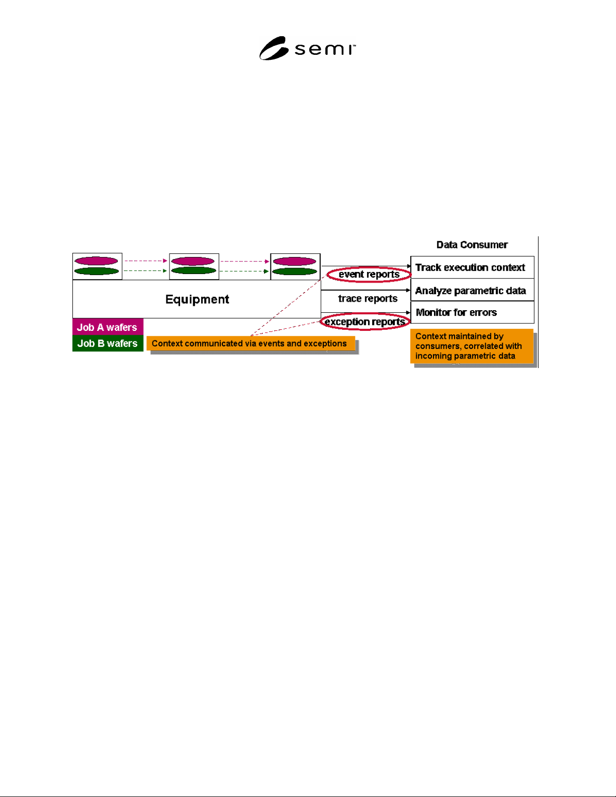
Figure R1-1
Typical Time-Series Data Analysis Example
R1-1.2.2 Consumers that collect trace data from the equipment need to be able to quickly make sense of incoming
data in order to determine the proper analysis and/or limits to apply. In addition to the raw low level data values
from sensors, actuators, and other devices of interest, applications need to be able to quickly determine the executing
context associated with that data. The equipment needs to be able to provide sufficient context information to the
application to allow it to determine at all times:
What module is the data coming from?
What recipe is that module running?
What step is that recipe executing?
What material is in that module?
What job is responsible for that material?
R1-1.2.3 In addition to the information in Section R1-1.2.2 , typical consumers must also know the manufacturing
execution context (for example, whether this an engineering lot, an experimental run, a characterization, a rework
lot, a production run, a specific product, etc.) in order to properly analyze data from the equipment. While it is the
consumer’s responsibility to manage this manufacturing context data, it is the equipment’s responsibility to provide
the context information described in Section R1-1.2.2 .
R1-1.2.4 In many cases, this context data may consist of a non-trivial amount of descriptive information. It is
typically not practical for all of this contextual data to be provided with each TraceReport sent by the equipment.
Trace data may also be collected at rates up to, for example, 10Hz; much more frequently than the rate at which the
job-related context information changes. Because of this situation, it is normally sufficient for the equipment to
communicate context changes when they happen by defining events that are generated whenever any of the context
described in Section R1-1.2.2 changes (see Figure R1-1).