semi合集-English.pdf - 第3905页
SEMI F30-0298 © SEMI 1998 3 12 Prepar ation of Apparatus 12.1 Sam pling System — Use appro p r ia te clean tubing and fittings , or clean before use. Purge system prior to samplin g. 12.2 Dynamic Diluti on System — U s e…
SEMI F30-0298 © SEMI 1998 2
10 Safety Precautions
10.1 The testing area should have adequate room
ventilation and atmospheric monitors.
10.2 Instruments should be exhausted to vent, and if
required in Class 1 environments, should be case-
purged or in an approved enclosure.
10.3 Testing personnel should be aware of customer
alarm and evacuation procedures.
10.4 Designated customer contact required during
testing.
11 Sampling
11.1 Test each purifier bed independently to verify
performance to customer specifications. Refer to gas
supplier’s certificate of conformance for inlet impurity
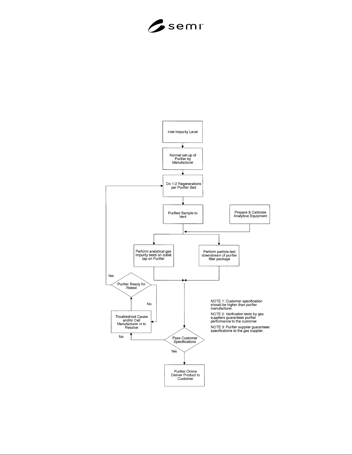
levels. Refer to Figure 1 for overall test sequence.
Figure 1
Overall Test Sequence

SEMI F30-0298 © SEMI 19983
12 Preparation of Apparatus
12.1 Sampling System — Use appropriate clean tubing
and fittings, or clean before use. Purge system prior to
sampling.
12.2 Dynamic Dilution System — Use certified
standards and dilute using equation (1) to calculate final
concentration (C
F
). For moisture, certified moisture
permeation devices can be used.
(1) C
c
× D.F. = C
F
C
c
= PPM - or PPB - certified cylinder standard concentration.
C
F
= final concentration.
D.F. = dilution factor which is calculated by taking the
flow (in liters) of the certified standard and dividing
by total flow (in liters). Dilution factors can be
multiplied in series, if diluting more than once.
Example 1: What is the final concentration for
dynamically diluting 10 ml of a 100 PPB impurity into
1 liter?
100 PPB × [0.010 liter/1.010 liter] = 0.99 PPB
12.2.1 Calibration should be done in the region
specified by the purifier manufacturer. For example, if
the purifier has an outlet impurity guarantee of 1 PPB
of each impurity, then the test equipment should be
calibrated with levels at approximately 1 PPB, not at 30
PPB and extrapolated down. Also, multipoint
calibration data is preferred.
12.3 APIMS, RGD-GC, ultratrace analytical
instrumentation. Particle counter.
12.3.1 Start-up and purge the instrumentation. Perform
calibration. Determine if calibration is satisfactory.
Proceed to sampling section.
12.4 Data Collection System — Check for proper
signal inputs, range inputs, and sampling intervals.
12.5 Data Reduction System — Prepare data as print-
outs and/or graphs. Include statistical analysis as
required. Generate final report.
13 Calibration and Standardization
13.1 See Section 12, Preparation of Apparatus.
14 Procedure
14.1 Trace Gas Impurity Measurement
14.1.1 Connect sample source to analytical equipment.
14.1.2 Start data collection.
14.1.3 Stop sampling. Review preliminary data. If it is
within customer specification, disconnect sample
source. If it does not meet specifications, investigate
cause or refer to manufacturer literature to resolve.
Once condition is corrected, repeat tests.
14.1.4 Repeat procedure for next bed or sampling
point. If instrumentation is relocated, calibration check
is required.
14.2 Particle Counting
14.2.1 Select sample location. Ideal location is a
permanently installed pitot probe.
14.2.2 Select where the particle tests will be done on
the pipe.
14.2.3 Use Reynold’s equation to determine the
required gas rate for turbulent flow to the particle
counter. Use this value or higher for sampling purposes.
Reynold’s number greater than 2100 are suggested for
turbulent flow.
14.2.4 Reduce incoming sample pressure to the
particle counter by following manufacturer’s
recommendation or by best practice.
14.2.5 Test particles with turbulent flow through
pipeline, if possible. However, do not exceed the
manufacturer’s maximum rated flow for the purifier.
14.2.6 Start data collection.
14.2.7 Stop sampling. Review preliminary data. If it is
within customer specification, disconnect sample
source. If it does not meet specifications, investigate
cause or refer to manufacturer’s literature to resolve.
Once condition is corrected, repeat tests.
14.2.8 Repeat procedure for next bed or sampling
point.
15 Calculations or Interpretation of Results
15.1 Results are interpreted by trending analysis,
averaging, or steady-state analysis.
16 Reporting Results
16.1 Sample location.
16.2 Operator identification.
16.3 Test parameters and conditions (pressures,
flowrates, temperatures, etc.).
16.4 Test date and duration.
16.5 Description of instrumentation.
16.6 Calibration information for analyzer(s).
16.7 Report test results by data table and/or graphs.
16.8 Comments on testing.
16.9 Conclusion.

SEMI F30-0298 © SEMI 1998 4
APPENDIX 1
NOTE: This appendix was approved as an official part of SEMI F30 by full letter ballot procedure.
Partial List of Analytical Equipment for Use in Oxygen Service
Impurity Analytical Equipment
H
2
O Dewpoint Detection
Electrolytic
Peizoelectric
Capacitance (aluminum oxide, silicon array)
Fourier Transform Infrared (FTIR)
CH
4
, Total Hydrocarbons,
Nonmethane Hydrocarbons
Flame-Ionization Detector-Gas Chromatograph (FID-GC)
Discharge Ionization Detector (DID)-GC
CO Reduction Gas Detector (RGD)-GC
Nondispersive Infrared (NDIR)
DID-GC
CO
2
Methanator on FID-GC
DID-GC
NDIR
H
2
RGD-GC
Particles Special counters required for O
2
service:
for 0.01 µ or greater, condensation nucleus counter
for 0.1 µ or greater, laser counter
NOTICE: These standards do not purport to address safety issues, if any, associated with their use. It is the
responsibility of the user of these standards to establish appropriate safety and health practices and determine the
applicability of regulatory limitations prior to use. SEMI makes no warranties or representations as to the suitability
of the standards set forth herein for any particular application. The determination of the suitability of the standard is
solely the responsibility of the user. Users are cautioned to refer to manufacturer’s instructions, product labels,
product data sheets, and other relevant literature respecting any materials mentioned herein. These standards are
subject to change without notice.
The user’s attention is called to the possibility that compliance with this standard may require use of copyrighted
material or of an invention covered by patent rights. By publication of this standard, SEMI takes no position
respecting the validity of any patent rights or copyrights asserted in connection with any item mentioned in this
standard. Users of this standard are expressly advised that determination of any such patent rights or copyrights, and
the risk of infringement of such rights, are entirely their own responsibility.
Copyright by SEMI® (Semiconductor Equipment and Materials
International), 3081 Zanker Road, San Jose, CA 95134. Reproduction o
f
the contents in whole or in part is forbidden without express written
consent of SEMI.