semi合集-English.pdf - 第842页
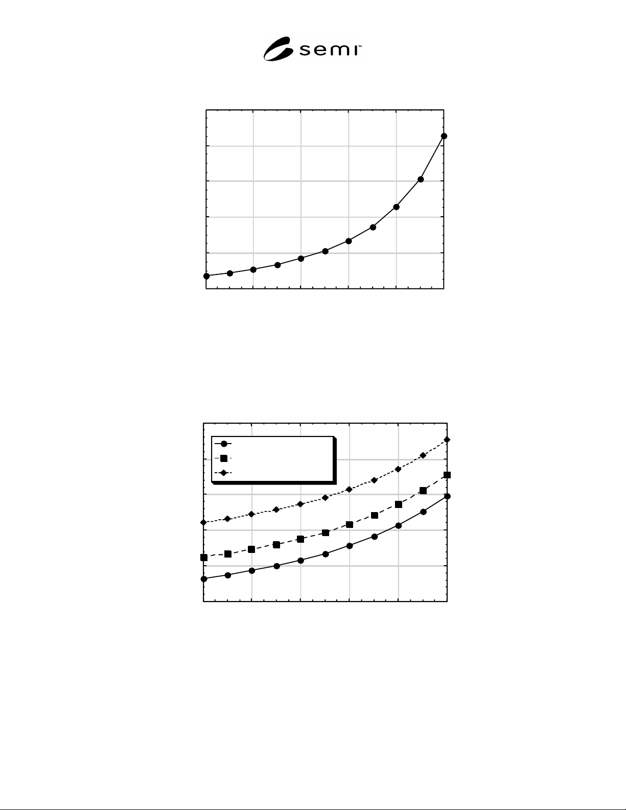
0.0 2.0 4.0 6.0 8.0 10.0 024 68 1 0 Real Load Impedance (ohms) Load Position (volts) Tune Position Fixed at 5.0 Volts NOTE: For this example, the full -scale voltage for both the Tune and Load Positi ons is 10 V (i.e., T…

coefficient measured at the output of the matching
network, when the input of the network is terminated
with both an open and a short circuit, shall vary less
than five percent in magnitude and phase at the
harmonic frequencies. Comparisons between networks
shall be made at three operating points, which include a
nominal operating point (e.g., at the midpoint of the
tuning range), a point within 10% of the maximum of
the tuning range, and a point within 10% of the
minimum operating range. Unless specifically
designed to, power dissipation in the network greater
than 10% (reflection coefficient of 0.95) at the
harmonic frequencies shall be avoided.
7.8.3 On those systems that have multiple RF
frequencies (i.e., one frequency for the source and
another frequency for the bias), the sensing circuits in
an automated matching network and the rf generators
shall ensure that the control signals are insensitive to
power in the other system frequencies and the
harmonics of all the system frequencies.
7.8.4 The supplier shall provide system verification
hardware (i.e., test fixtures/interfaces) for system
verification after assembly and delivery. Nominally,
this hardware shall be in the form of a nominal coaxial
connector interface (e.g., type “N” connector) for ease
of measurement. Example fixtures would include those
for interfacing with the RF applicator/interface (i.e.,
chuck assembly or coil input) and the output of the
matching network. The supplier shall provide
recommended test methods and/or procedures for
system verification.
8 Related Documents
8.1 IEEE Standards
3
IEE-STD-572 — IEEE Standard for Qualification of
Class 1E Connection Assemblies for Nuclear Power
Generating Stations
IEEE C95.1 — IEEE Standard for Safety Levels with
Respect to Human Exposure to Radio Frequency
Electromagnetic Fields, 3 kHz to 300 GHz
8.2 Federal Communications Commission (FCC)
4
FCC 47CFR1.1310 — Radio frequency radiation
exposure limits
FCC 47CFR2 Part 2 — Frequency Allocations and
Radio Treaty Matters; General Rules and Regulations
3 Institute of Electrical and Electronics Engineers, IEEE Operations
Center, 445 Hoes Lane, P.O. Box 1331, Piscataway, New Jersey
08855-1331, USA. Telephone: 732.981.0060; Fax: 732.981.1721
website: www.ieee.org
4 United States Federal Communications Commission, 445 12th St.
S.W., Washington DC 20554, Website: www.fcc.gov
FCC 47CFR2 Part 2 Subpart J — Equipment
Authorization Procedures
8.3 MIL-Specifications
5
MIL-PRF-31031A — General Specification for
Connectors, Electrical, Plugs and Receptacles, Coaxial,
Radio Frequency, High Reliability, for Flexible and
Semirigid Cables
MIL-STD-348A — Radio Frequency Connector
Interfaces for MIL-C-3643, MIL-C-3650, MIL-C-3655,
MIL-C-25516, MIL-C-26637, MIL-PRF-39012, MIL-
PRF-49142, MIL-PRF-55339, and MIL C-83517
MIL-DTL-28875A — General Specification for
Amplifiers, Radio-Frequency and Microwave, Solid-
State
MIL-T-28732C — General Specification for
Transformer, Impedance Matching, Balanced to
Unbalanced (Balun)
MIL-STD-220B — Test Method Standard: Method of
Insertion Loss Measurement
8.4 International Emissions Standards
FCC CFR47 Part 18 — Industrial, Scientific and
Medical (ISM) Equipment (United States)
4
DIN EN 55011 — Industrial, scientific and medical
(ISM) radio-frequency equipment - Radio disturbance
characteristics - Limits and methods of measurement
6
V-2/97.04 — Regulations for Voluntary Control
Measures
7
CNS 13438 — Limits and Methods of Measurement of
Radio Disturbance Characteristics of Information
Technology Equipment
8
NOTICE: Unless otherwise indicated, all documents
cited shall be the latest published versions.
5 Naval Publication and Forms Center, 5801 Tabor Avenue,
Philadelphia PA 19120 U.S.A Available from website:
www.dodssp.daps.mil/products.htm
6 Available from Deutches Institut für Normung e.V., Beuth Verlag
GmbH, Burggrafenstrasse 4-10, D-10787 Berlin, Germany, website:
www.din.de
7 Voluntary Control Council for Interference by Information
Technology Equipment, website: http://www.vcci.or.jp
8 Chinese National Standards, Available from NSSN
(http://www.nssn.org) as Document CNS C6035700
SEMI E113-1104 © SEMI 2001, 2004 7
0.0
2.0
4.0
6.0
8.0
10.0
0246810
Real Load Impedance (ohms)
Load Position (volts)
Tune Position Fixed at 5.0 Volts
NOTE: For this example, the full-scale voltage for both the Tune and Load Positions is 10 V (i.e., Tune = 5.0 V corresponds to
50% of full scale).
Figure 1
Example Plot of the Real Part of the Load Impedance as a Function of the Load Position Tuning Element in
the Matching Network
-35.0
-30.0
-25.0
-20.0
-15.0
-10.0
0246810
Tune = 3.0 volts
Tune = 5.0 volts
Tune = 7.0 volts
Reactive Load Impedance (ohms)
Load Position (volts)
NOTE: The Tune Position is at the indicated fixed value for each set of data. For this example, the full-scale voltage for both the
Tune and Load Positions is 10 V (i.e., Tune = 3.0 V corresponds to 30% of full scale).
Figure 2
Example Plot of the Reactive Part of the Load Impedance as a Function of the Load Position Tuning Element
in the Matching Network
SEMI E113-1104 © SEMI 2001, 2004 8
50.0
60.0
70.0
80.0
90.0
100.0
0246810
Tune = 3.0 volts
Tune = 5.0 volts
Tune = 7.0 volts
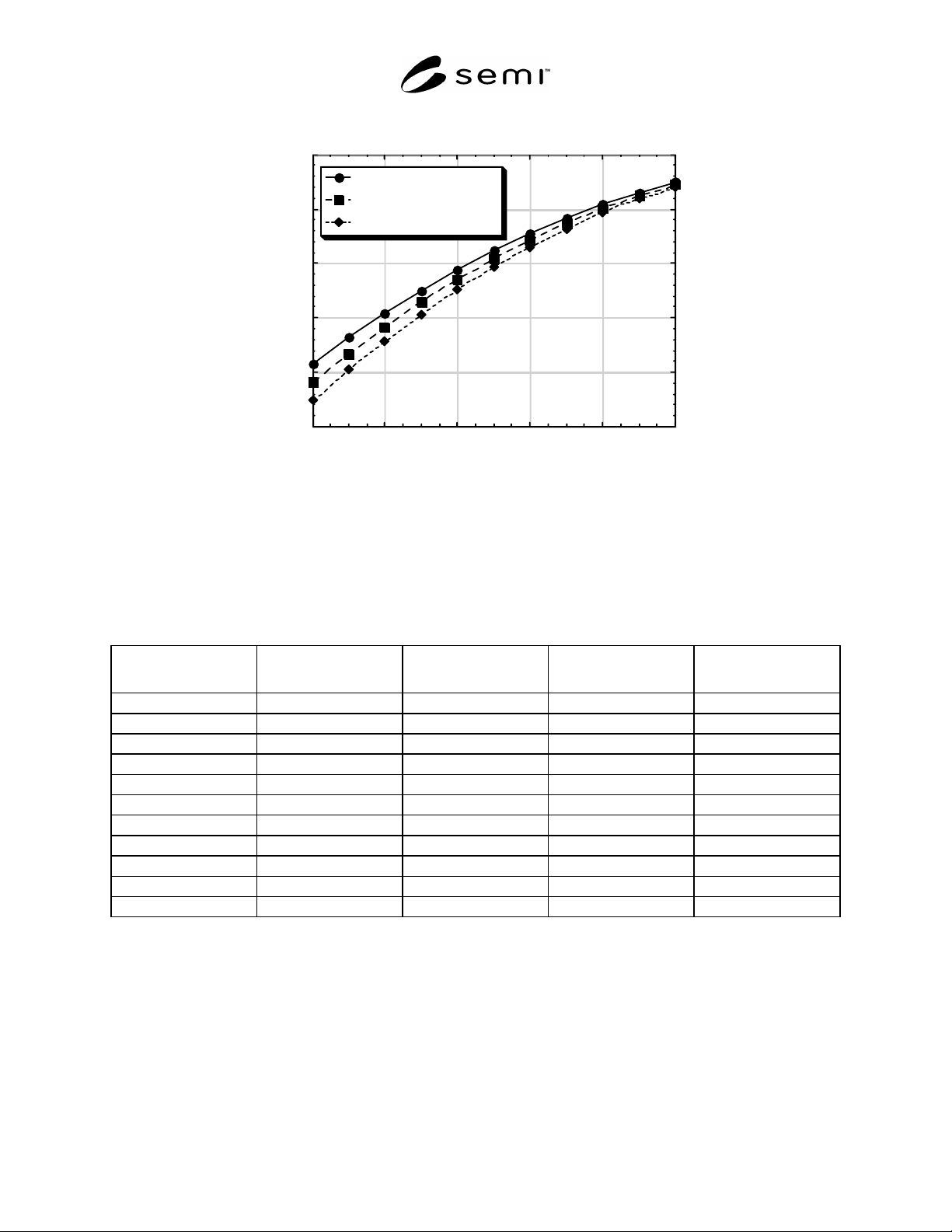
Power Efficiency (%)
Load Position (volts)
NOTE 1: The Tune Position is at the indicated fixed value for each set of data. For this example, the full-scale voltage for both
the Tune and Load Positions is 10 V (i.e., Tune = 3.0 V corresponds to 30% of full scale).
Figure 3
Example Plot of the Power Efficiency as a Function of the Load Position Tuning Element in the Matching
Network
Table 1 Example Data Table Showing the Matching Network Load Impedance and Power Efficiency as a
Function of the Positions of the Tuning Elements
Load
Position, volts
Tune
Position, volts
Real Load, ohms Reactive Load, ohms Power Efficiency, %
0 3 0.74 –31.75 61.51
1 3 0.91 –31.23 66.36
2 3 1.12 –30.64 70.86
3 3 1.38 –29.96 75.04
4 3 1.72 –29.18 78.88
5 3 2.15 –28.26 82.38
6 3 2.72 –27.17 85.56
7 3 3.50 –25.87 88.39
8 3 4.59 –24.31 90.90
9 3 6.18 –22.42 93.07
10 3 8.57 –20.15 94.91
NOTE 1: For this example, the full-scale voltage for both the Tune and Load Positions is 10 V (i.e., Tune = 3.0 V corresponds to 30% of full
scale). This example only shows data for a fixed Tune position of 3.0 volts. Data is also required at a Tune position of 0.0 V, 1.0 V, etc.
SEMI E113-1104 © SEMI 2001, 2004 9