semi合集-English.pdf - 第516页
SEMI E74-0301 © SEMI 1998 , 2001 5 unde r 2 s eco nds accel eratio n status(o utput) close open close open start signal (input) Response Tim e and Timing for Cont rol Sig nals (delay an d/o r dead ti me) Under 50 mill is…
SEMI E74-0301 © SEMI 1998, 2001 4
6.2 Electrical Interfaces
6.2.1 Control Signals
6.2.1.1 Table 3.1 specifies the required TMP control signals. In cases where TMP are backed up by battery or
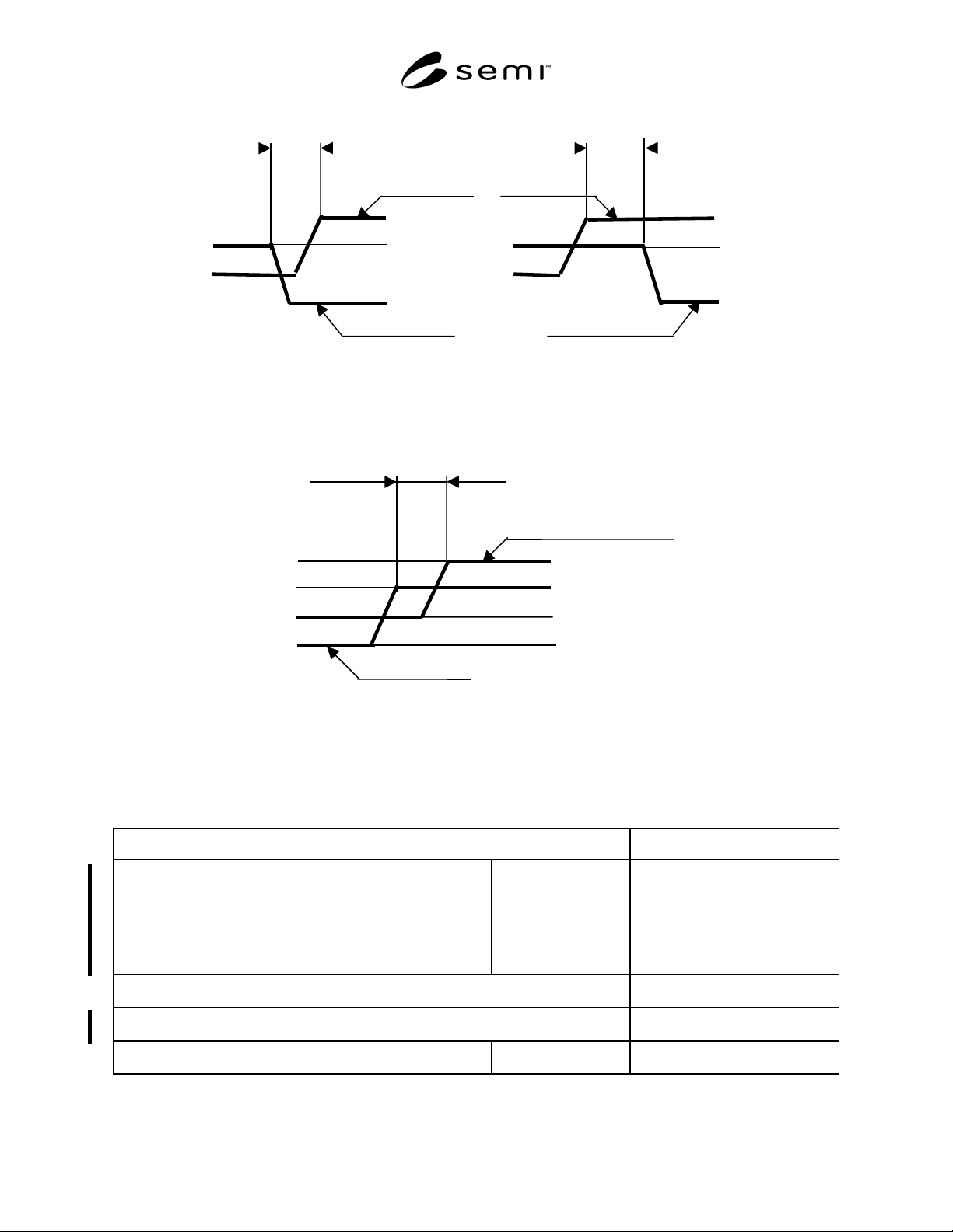
regeneration power while input power failure, the status of output signals follows Table 3.2. Table 4 and Figure 3
specify the required response time for TMP control signals. Table 5 specifies the required power and contacts for
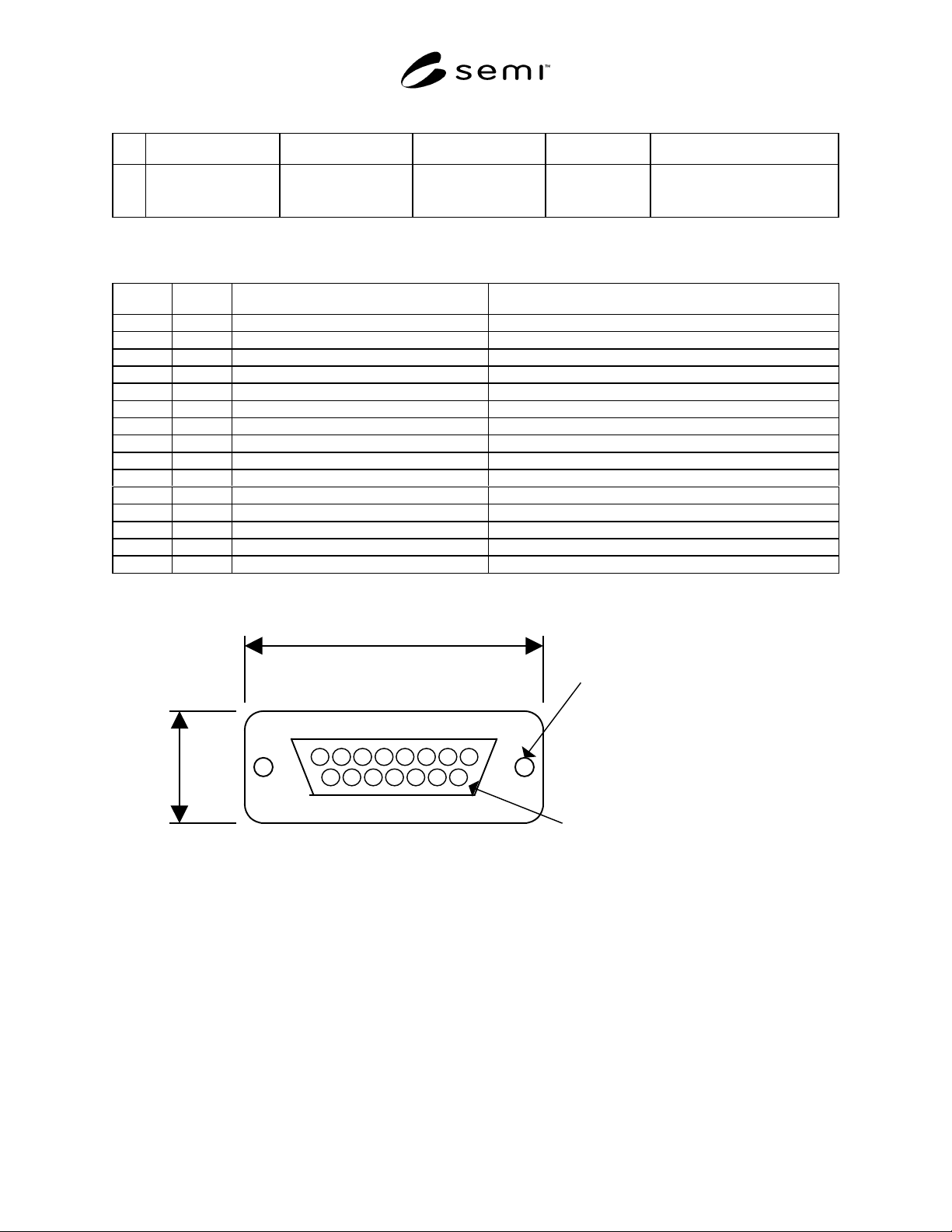
TMP control signals. Tables 6 and 7 and Figure 4 specify the required connector and pin assignments for TMP
control signals.
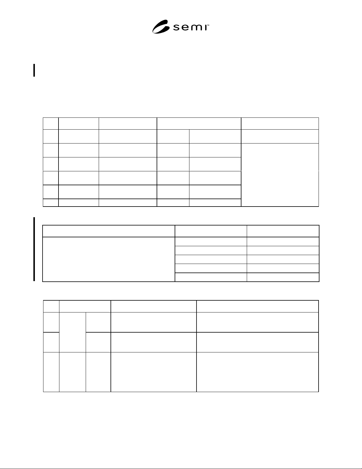
Table 3.1 I/O Signals
No. Signal Name Direction Type Remarks
1 Start (Run)/Stop Input signal to Pump Alternate Pump runs when
closed
2 Acceleration Output signal from Pump Alternate Close during
acceleration
3 Normal operation Output signal from Pump Alternate Close during normal
operation
4 Deceleration Output signal from Pump Alternate Close during
deceleration
5 Remote/Local Output signal from Pump Alternate Close during remote
operation
6 Pump Alarm Output signal from Pump Alternate Open at alarm
Running status signals
When input power is OFF, output
status signals should become open
(normally open).
Table 3.2 Status of output signals during back up operation mode
Status of pump Signal Name Status of signals
Acceleration Open
Normal operation Open
Deceleration Close
Remote/Local Close during remote operation
During back up operation mode
Pump alarm Open
Table 4 Response Time and Timing for Signals
No. Items Acceptable Response Time Remarks
1 Input
Power
ON
Under 10 seconds
After input power turns on
Objects
All status signals shall be ready.
2
Response
Time
Control
Signals
Under 2 seconds
After receiving a signal
Objects
Start signal (input) ->> Acceleration (output)
Stop signal (input) ->> Deceleration (output)
3 Timing Running
status
signals
Under 50 milliseconds
Acceptable delay and/or dead time in a
moment of shift of the running status
Under 50 milliseconds
Acceptable overlapped time in a
moment of shift of the running status
Objects (Example)
Normal ->> Deceleration
The running status signals of alarm and remote/local
can be overlapped with other signals.
SEMI E74-0301 © SEMI 1998, 20015
under 2 seconds
acceleration status(output)
close
open
close
open
start signal (input)
Response Time and Timing for Control Signals
(delay and/o
r
dead time)
Under 50 milliseconds
(Overlapped time of
signal)
deceleration
normal operation
open
close
Timing for the running status signals
close
open
normal operation
open
close
close
open
deceleration
Under 50 milliseconds
Figure 3
Response Time and Timing for Control Signals
Table 5 Signal Power and Contacts
No. Items Power Remarks
Input signals to TMP
(Control signal)
Input signals shall be
driven by DC power
supply in TMP.
Example: See Figure 5.
a) Photocoupler Input.
b) Relay Input.
1
Signal power supply
Output signals from
TMP (Running status
signal)
Output signals shall be
driven by DC power
supply in tools.
Example: See Figure 6.
a) To photocoupler unit.
b) To relay unit.
c) To TTL unit.
2
Signal power supply voltage Signal power supply voltage is between 5 V
DC
and 24 V
DC
3
Acceptable range of signal power
supply voltage
Acceptable voltage range is 4 V
DC
minimum
and 30 V
DC
maximum.
4
Running status signal contact Dry contact or open
collector
Acceptable current 100
mA maximum.
SEMI E74-0301 © SEMI 1998, 2001 6
Table 6 Control Signal Connector (Pump Side)
No. Items Connector Type Referenced Standard Pin Assignments Remarks
1 Control and running
status signals
15 pin
D sub-miniature
Female receptacle
See Table 7 and
Figure 4
(See Related Documents for an
example of the specification for
this connector type.)
Table 7 Pin Assignment for Control Signal Connector
No. Pin No. Signal item (polarity) Remarks
1 1 Start/Stop input ( + )
22
3 3 Acceleration status ( + )
4 4 Normal status ( + )
5 5 Deceleration status ( + )
6 6 Alarm status ( + )
7 7 Remote/Local status ( + )
88
9 9 Start/Stop input ( - )
10 10
11 11 Acceleration status ( - )
12 12 Normal status ( - )
13 13 Deceleration status ( - )
14 14 Alarm status ( - )
15 15 Remote/Local status ( - )
MAX. 45.1 mm
MAX. 18.0 mm
Screw lock size : M2.6
Contact pin surface : Au
Figure 4
15 pin D sub-Miniature Female Receptacle