semi合集-English.pdf - 第2967页
SEMI E120-0705 © SEMI 2003, 2005 3 6.2.6 Constraint s 6.2.6.1 Constraints in UML a re shown wit h dotted lines, typical ly with a no te attached to explain the constrain t. Constraints shown in this way ten d to clutter …
SEMI E120-0705 © SEMI 2003, 2005 2
5.2 Definitions
5.2.1 UML terms used in this document conform to definitions in the Glossary of Terms of the OMG specification
of UML (referenced above). Related Information, §R1, contains selected definitions from that Glossary of Terms.
5.2.2 Definitions or descriptions of many of the terms used in this specification can be found in the SEMI
Compilation of Terms, available on the SEMI web site, http://www.semi.org/.
5.2.3 When terms from the above two sources conflict, the definition from the OMG UML specification takes
precedence in this specification.
6 Conventions
6.1 This section defines conventions followed in this document.
6.2 Object Modeling
6.2.1 Unified Modeling Language (UML) — This specification uses UML notation for all class diagrams and for
object diagrams provided as examples. No other types of diagrams are used in this specification.
6.2.1.1 UML class diagrams have clearly defined meaning and are a part of this specification. Detail contained in
these diagrams is not always repeated in the text.
6.2.2 Behavior Not Defined — This specification, defines classes, their relationships, and attributes. No behavior is
specified either in the form of UML state, activity, sequence diagrams, or in the form of operations definitions.
6.2.3 Name of a Class — The text capitalizes class names.
6.2.4 Abstract and Concrete Classes — Each class is specified as Abstract or Concrete. Abstract classes are not
directly implemented. In this specification “implemented” means represented to the factory through the
communications interface. All classes defined as concrete may be directly implemented. This specification does
not attempt to define equipment control system implementation. In UML class diagrams, abstract class names are
shown in italics.
6.2.5 Class Attribute Definition — The attributes of a class are defined in table format as illustrated by Table 1
below. Note that the “+” sign in front of attributes in UML class diagrams indicates “public” attributes. All
attributes defined in this specification are public.
Table 1 Attribute Table Format
Attribute Name Definition Access Reqd Form
RO or
RW
Y or
N
See list below.
6.2.5.1 Access — Attributes may be settable (ReadWrite or RW) or not settable (ReadOnly or RO) through an
interface to the equipment.
6.2.5.2 Reqd — Is this attribute required? Y – Yes, or N – No.
6.2.5.3 Form — Defines the data type of the attribute. Data types specified in the Common Equipment Model
specification are described in the subsections that follow. Data types in this specification are high-level definitions
and should be mapped to the data types of a specific technology as appropriate. Extensions to the Common
Equipment Model are not limited to the list of data types defined in this specification. See the definition of “Form”
in the SEMI Compilation of Terms for other Form values commonly used in SEMI documents.
6.2.5.3.1 Enumeration — A list of named values used as the range of a particular attribute type. In this document,
these values are represented as text strings, but may be implemented differently (e.g. as integers that correspond to
the named values).
6.2.5.3.2 String — A text string. Limitations on length are left to the implementation technology unless otherwise
specified in this document.
6.2.5.3.3 List of xxx — An item that can hold multiple instances of a specified type (where xxx is the data type).
SEMI E120-0705 © SEMI 2003, 2005 3
6.2.6 Constraints
6.2.6.1 Constraints in UML are shown with dotted lines, typically with a note attached to explain the constraint.
Constraints shown in this way tend to clutter large UML diagrams. Therefore, in this specification, constraints are
shown only on the diagrams focusing on individual classes.
6.2.7 Association Navigability
6.2.7.1 UML associations include the concept of “Navigability”. When an association is navigable, the association
may be traversed to reach the class instance at the opposite end of the association (target object).
6.2.7.2 By default, an association is navigable in both directions. If an arrowhead is shown on one end of an
association, then navigability exists only in that direction.
6.2.7.3 From any object, it must be possible to obtain a reference to the target objects of any of its navigable
associations.
6.2.7.4 The method of referencing the target objects is implementation dependent and is not specified in this
document.
6.2.7.5 Any implementer or subordinate standards mapping the concepts of this specification to an implementation
method shall specify the means of referencing the target object of an association from the source object.
6.3 Model Extension
6.3.1 Any concrete class in the CEM model can be extended. Extension is achieved through association. In
“extension by association” the new capability is contained in a separate class that is related to the original by an
association. In the case of CEM, an “Extension” class has been added to the model (see ¶8.5.3.4) along with the
needed association.
6.3.2 The Extension class is associated with Nameable, so that any Nameable can have multiple Extensions. The
Extension class has no attributes or services and does not itself add anything to the extended CEM class. To have a
meaningful extension, a subclass of Extension must be created containing the new features.
6.3.3 So, in order to create an extension to a selected concrete CEM class, a new class would be designed with
added features. For instance, it might contain a new attribute. This new class would be designed as a subclass of
Extension. Remember that any Nameable can navigate the association to any of its Extensions. Therefore, the new
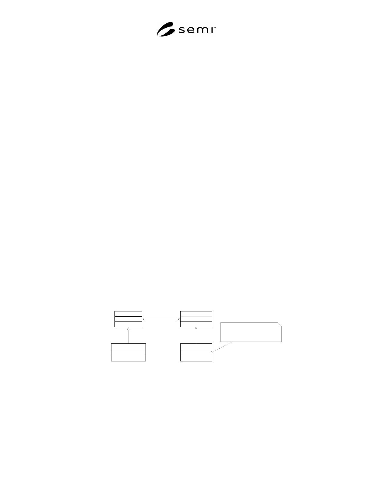
subclass of Extension could be associated with any CEM class. See Figure 1 below for an illustration. The final
step is to associate the new Extension subclass to the specific CEM class it is extending.
6.3.4 Most extensions will be designed to work on specific CEM classes. The CEM model does not enforce
matching an extension with its intended CEM class. Therefore, the specification of the Extension class must
describe its allowed usage.
Nameable
Extension
extensions
0..*
CEMClass
NewAttribute:string
CEMClassExtension
CEMClass inherits the association with
Extensions - it may have an associated
CEMClassExtension and thus gain
access to the NewAttribute
1
target
Figure 1
CEM Model Extension
6.3.5 The scope of CEM is limited to static information about the equipment. However, that limitation does not
apply to extensions. So extensions might include static or dynamic attributes as well as links to state models or
other complex constructs. An example of an extension that might be added by a supplier is a class containing
“manufacturedDate” and “serviceTagNumber” attributes to be applied to an Equipment object.
SEMI E120-0705 © SEMI 2003, 2005 4
7 Background
7.1 This specification documents common characteristics of equipment in a single specification that can be
referenced and used by other standards. These other standards are expected to extend the Common Equipment
Model to add characteristics unique to that standard. Thus, this specification attempts to be the core of a single,
coordinated object model of the equipment with the full model being a composite of multiple standards.
7.2 Approach to Model Description
7.2.1 Class Model vs. Instance Model
7.2.1.1 A model showing the specifics about particular equipment is considered an “instance model”. Each
equipment instance model will have its own characteristics based on its function. No single model can directly
describe all such instances. Instead, the class model contained in this specification defines the classes to be used to
describe the equipment’s structure and how they shall relate to one another. The instance model of the equipment is
to be provided by the equipment supplier as specified by the CEM class model.
7.2.2 Model Extensibility
7.2.2.1 The Common Equipment Model is intended to be extensible (within defined limits). ¶6.3 describes
acceptable ways to extend the model.
7.2.2.2 The instance model of the equipment shall thus be constructed by the equipment supplier based on
the classes defined in this document,
extensions to this model defined in other SEMI standards, and
extensions to the standardized model made by the supplier to address unique equipment characteristics.
7.2.3 External View — Not Equipment Design
7.2.3.1 There is no expectation that equipment suppliers will use the model specified in this document as the basis
for the design of their equipment. The CEM is intended to provide a structure to promote clear communication. It
needs to provide an unambiguous view to the factory host that is representative of the equipment and meets the
needs of the host.
7.2.4 Communication Not Defined
7.2.4.1 This specification leaves to other SEMI standards the definition of how the Common Equipment Model will
be communicated (in whole or in part) between the equipment and the factory host. It is to be expected that there
will be many uses for the model and the details of communication are best defined in context with planned use.
7.2.5 Behavior Not Defined
7.2.5.1 In order to keep the model simple, this document does not define behavior of classes in the CEM. Class
behavior is related to function, and thus to functionality supplied by the equipment interface. This functionality and
behavior is left to other SEMI standards to define.
7.2.6 Applicability
7.2.6.1 Though the CEM attempts to address all semiconductor related factory equipment, it is recognized that this
may not be possible. The CEM covers only manufacturing equipment (i.e. equipment that perform their function on
material—e.g. no independent environmental monitoring systems, etc.). The vast majority of semiconductor factory
equipment should be able to comply with this specification.
7.3 Uses For The CEM
7.3.1 In order to understand the CEM, it is necessary to understand expected uses of the model. While it is not
possible to anticipate every possible use, the following list presents several expected uses that may be defined by
other standards.
7.3.2
Equipment Self-Description Using Metadata — An important consideration for the integration of
semiconductor equipment into the factory is the ease with which the equipment’s structure and capabilities can be
understood and translated into functioning software. With traditional semiconductor communication technologies
this is achieved by first reading the equipment supplier’s communication manual and then configuring or coding