semi合集-English.pdf - 第6242页
SEMI G47-88 © SEMI 1988 9 Ta ble 4 ( see Figur e 7) Guide lines fo r P lace ment o f Tap ing Di mensio ns 84 Lead Thr ough 196 Leadframes 1. No min al tape width ma ximum — 0.037" 2. No min al tape width ma ximum — …
SEMI G47-88 © SEMI 1988 8
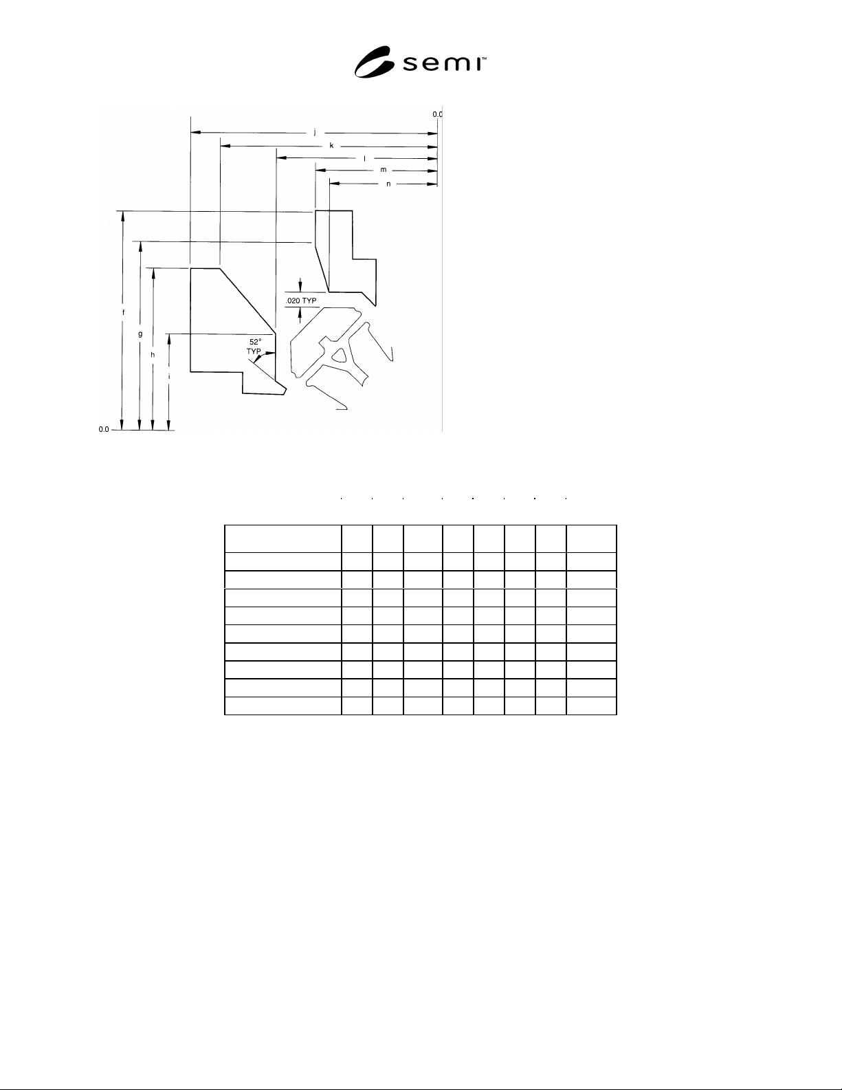
Detail C Gate Relief
Table 4
Lead Count 52 68 84 100 132 164 196 244
f 0.435 0.485 0.535 0.585 0.685 0.785 0.885 T.B.D.
g 0.394 0.444 0.494 0.544 0.644 0.744 0.844 T.B.D.
h 0.360 0.410 0.460 0.510 0.610 0.710 0.810 T.B.D.
i 0.272 0.322 0.372 0.422 0.522 0.622 0.722 T.B.D.
j 0.435 0.485 0.535 0.585 0.685 0.785 0.885 T.B.D.
k 0.399 0.449 0.499 0.549 0.649 0.749 0.849 T.B.D.
l 0.325 0.375 0.4325 0.475 0.575 0.675 0.775 T.B.D.
m 0.269 0.319 0.369 0.419 0.519 0.619 0.719 T.B.D.
n 0.253 0.303 0.353 0.403 0.503 0.603 0.703 T.B.D.
SEMI G47-88 © SEMI 19889
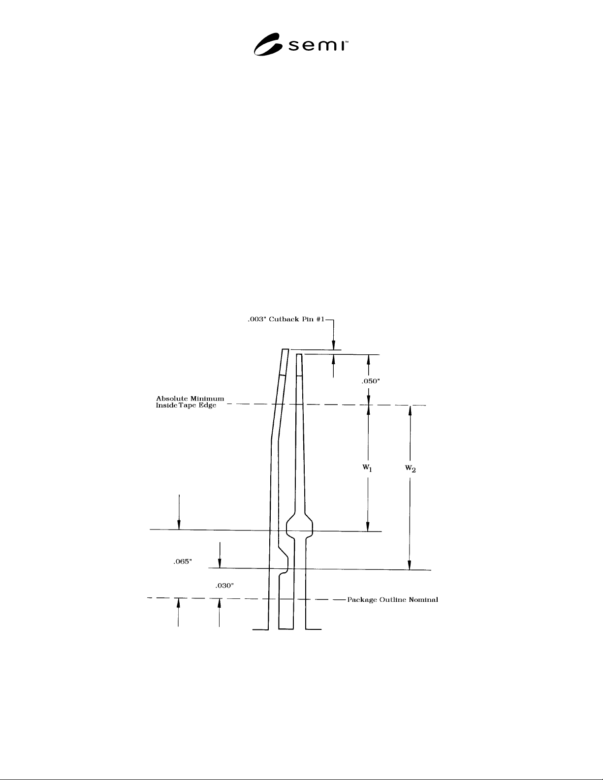
Table 4 (see Figure 7) Guidelines for Placement of Taping Dimensions 84 Lead Through 196 Leadframes
1. Nominal tape width maximum — 0.037"
2. Nominal tape width maximum — 0.060"
3. Tape width tolerance — ± 0.003"
4. Tape location tolerance — ± 0.015"
5. Absolute minimum location of outside tape edge from lead tip — 0.050".
6. Minimum location of outside tape edge from package outline nominal dimension — 0.065".
7. When window “W1” dimension cannot be met with minimum tape nominal width and recommended tolerancing
which is the case with various given pad sizes of different lead counts, window “W2” dimension, 0.030", from
package outline nominal should be used for the outside tape limit. If this window “W2” dimension still cannot be
met negotiation of tape width and location tolerances between supplier and purchaser is suggested to maintain
tape within the recommended window dimensions.
8. Recommended center line of tape for nominal location is midway between inside and outside tape edge limits for
window “W1” & window “W2” dimensions as appropriate and within tolerance limits.
9. Downset angle — 30°
10.Downsetting must begin inside 0.025" minimum flat distance along tie bar from inside edge of applied tape.
11.Recommended downset length is maximum allowable within the above guidelines.
Figure 7

SEMI G47-88 © SEMI 1988 10
NOTICE: These standards do not purport to address
safety issues, if any, associated with their use. It is the
responsibility of the user of these standards to establish
appropriate safety and health practices and determine
the applicability of regulatory limitations prior to use.
SEMI makes no warranties or representations as to the
suitability of the standards set forth herein for any
particular application. The determination of the
suitability of the standard is solely the responsibility of
the user. Users are cautioned to refer to manufacturer’s
instructions, product labels, product data sheets, and
other relevant literature respecting any materials
mentioned herein. These standards are subject to
change without notice.
The user’s attention is called to the possibility that
compliance with this standard may require use of
copyrighted material or of an invention covered by
patent rights. By publication of this standard, SEMI
takes no position respecting the validity of any patent
rights or copyrights asserted in connection with any
item mentioned in this standard. Users of this standard
are expressly advised that determination of any such
patent rights or copyrights, and the risk of infringement
of such rights, are entirely their own responsibility.
Copyright by SEMI® (Semiconductor Equipment and Materials
International), 3081 Zanker Road, San Jose, CA 95134. Reproduction o
f
the contents in whole or in part is forbidden without express written
consent of SEMI.