semi合集-English.pdf - 第4788页
3 SEMI C55-1104 © SEMI 2004 8.1.5 Operating Procedure 8.1.5.1 Follow the procedures specified in the instrument m anufacturer’s manual. 8.1.5.2 Allow th e system to run until a stable reading is obtained for 2 0 minutes.…
SEMI C55-1104 © SEMI 2004 2
7 Physical Constants
7.1 The physical constants of carbon dioxide are given
in Table 2 (for information only).
Table 2 Physical Constants (for information only)
Metric Units US Units
Molecular Weight 44.01 44.01
Sublimation Point at 1
atm (14.7 psia)
-78.5
o
C -109.3
o
F
Triple Point Temperature -56.6
o
C -69.9
o
F
Triple Point Pressure 5.1 atm 75.1 psia
Critical Temperature 31
o
C 87.8
o
F
Minimum Near Critical
Temperature
-45.0
o
C -49.1
o
F
Critical Pressure 73 atm 1070 psia
Density of gas at 21.1
o
C
(70
o
F) and 1 atm
1.823 kg/m
3
0.1138 lb/ft
3
Density of Saturated
Liquid at 25
o
C
713 kg/m
3
44.5 lb/ft
3
8 Analytical Procedures
8.1 Water — This procedure is for the determination of
trace moisture (water) in carbon dioxide using an
analyzer, such as a continuous flowing phosphorus
pentoxide hygrometer.
8.1.1 Detection Limit — 100 ppbv or better
8.1.2 Instrument Parameters
8.1.2.1 Flow Requirements — Use appropriate flow, as
recommended by manufacturer.
8.1.3 Calibration Standard — The analyzer shall be
calibrated by reference to a standard gas calibration
mixture containing a moisture content close to the
expected value of the gas under test, in accordance with
the instrument manufacturer’s instructions. This
calibration standard may be prepared using the
procedure described in SEMI F33, Sections 13.2.2 and
13.2.3 and tested using the procedure described in
SEMI C15.
8.1.4 Sample System
8.1.4.1 The sample line and associated valves must be
clean and moisture free. They must be constructed
from high cleanliness materials, such as electropolished
stainless steel. The sample line should be purged dry if
exposed to ambient moisture. The baseline moisture
level should be less than 0.1 ppm.
8.1.4.2 Draw a continuous liquid sample from the
source. The sample line should be insulated so that the
sample does not boil due to heat infiltration. The
distance between the sample point and the analyzer
should be as small as possible to minimize boil-off.
8.1.4.3 Heat the sample so that it is completely
vaporized, leaving absolutely no liquid or solid carbon
dioxide or water residue.
8.1.4.4 Maintain the sample temperature at the
analyzer inlet above its condensation point. A sample
temperature of 40
o
C is recommended.
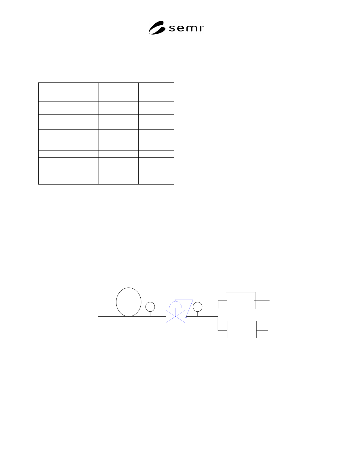
8.1.4.5 Figure 1 illustrates one potential sampling
configuration.
FROM
LIQUID
CO2
SYSTEM
VENT
VENT
HEATED
TUBING
THERMOCOUPLE
FORWARD
PRESSURE
REGULATOR
PRESSURE
GAGE
THC
DETECTOR
MOISTURE
A
NALYZE
R
Figure 1
Potential Hydrocarbon and Water Sampling System

3 SEMI C55-1104 © SEMI 2004
8.1.5 Operating Procedure
8.1.5.1 Follow the procedures specified in the
instrument manufacturer’s manual.
8.1.5.2 Allow the system to run until a stable reading is
obtained for 20 minutes.
8.1.5.3 Read and record the concentration of moisture
indicated on the moisture analyzer, in ppmv. The result
obtained shall not exceed the value specified in Section
5 of this specification.
8.2 Total Hydrocarbons — This procedure is for the
determination of total hydrocarbons expressed as
methane in carbon dioxide using a total hydrocarbon
analyzer.
8.2.1 Detection Limit — 100 ppbv or better.
8.2.2 Instrument Parameters
8.2.2.1 Flow Requirements — Use appropriate flow, as
recommended by manufacturer.
8.2.3 Calibration Standard — 1 ppmv methane in
nitrogen.
8.2.4 Sampling System
8.2.4.1 The sample line and associated valves must be
clean and hydrocarbon free. They must be constructed
from high cleanliness materials, such as electropolished
stainless steel. The sample line should be cleaned if
exposed to hydrocarbons, such as oils or greases.
8.2.4.2 Draw a continuous liquid sample from the
source. The sample line should be insulated so that the
sample does not boil due to heat infiltration. The
distance between the sample point and the analyzer
should be as small as possible to minimize boil-off.
8.2.4.3 Heat the sample so that it is completely
vaporized, leaving absolutely no liquid or solid carbon
dioxide or water residue. Note that if detection of
heavy hydrocarbons (>C10) is important, it may not be
feasible to completely vaporize the sample. Therefore,
a concentrator method, such as that described in ASTM
E 1747, Section 6, may be required.
8.2.4.4 Maintain the sample temperature at the
analyzer inlet above its condensation point. A sample
temperature of 40
o
C is recommended.
8.2.4.5 Figure 1 illustrates one potential sampling
configuration.
8.2.5 Operating Procedure
8.2.5.1 Follow the procedures specified in the
instrument manufacturer’s manual.
8.2.5.2 Allow the system to run until a stable reading is
obtained for 20 minutes.
8.2.5.3 Read and record the concentration of
hydrocarbons as methane indicated on the total
hydrocarbon analyzer, in ppmv. The result obtained
shall not exceed the value specified in Section 5 of this
specification.
8.3 Metals — This procedure is for the determination
of insoluble and soluble metals in carbon dioxide using
inductively coupled plasma-mass spectroscopy (ICP-
MS), ICP-AES. Specific components to be monitored
are Na, Fe, Ni, Cu, Cr, Co, Mn, Ca, Mo and W.
NOTE 2: The specified method does not detect volatile
metals.
8.3.1 Detection Limit — Determined per SEMI C10.
8.3.2 Instrument Parameters
8.3.3 Calibration Standards — Consult with
instrument manufacturer instructions. All instrument
calibration standards should be prepared from NIST-
traceable reference standards.
8.3.4 Sampling System
8.3.4.1 Two sample preparation methods are approved
for metals analysis. These are a residue method and a
filtration method. The user may select between these
techniques based on convenience, economic
considerations, or other situation specific conditions.
8.3.4.1.1 Residue Method — A CO
2
sample is
transferred to an ambient pressure vessel and allowed to
sublime. The remaining metal residue is dissolved in
nitric acid.
8.3.4.1.1.1 The sample line and associated valves must
be clean and metal particle free. They must be
constructed from high cleanliness materials, such as
electropolished stainless steel.
8.3.4.1.1.2 The sample system must be purged with
high-purity nitrogen prior to and after sampling. Prior
to sampling, the entire sampling system should be
purged by allowing high purity nitrogen to flow through
the system at 5–10 psig for a minimum of three
minutes.
8.3.4.1.1.3 When the purge is complete, draw a
sufficient mass of liquid carbon dioxide sample from
the source to obtain a meaningful metals level. A valve
should be installed in the sample line to flash the liquid
sample from the operating pressure to near ambient
pressure. This will cause the sample to form a
solid/vapor mixture. This mixture should then be
directed to the bottom of a vented sample flask. The
sample flask should have a volume of 100 ml and
should be composed of polypropylene or other suitable
materials. It should be cleaned prior to use using DI
water.

SEMI C55-1104 © SEMI 2004 4
8.3.4.1.1.4 Solid CO
2
and any metals will deposit in
the sample flask. When sampling is complete, the
resulting solid CO
2
should be allowed to warm to
ambient temperature and sublime. As a result, vapor
CO
2
will leave the sample flask.
8.3.4.1.1.5 After all of the CO
2
has been vented from
the sample flask, the system should be purged with
nitrogen for 15 minutes.
8.3.4.1.1.6 The sample flask should then be filled with
a solution of 5% ultrapure HNO
3
/DI H
2
O. This
solution may be spiked with an appropriate internal
standard. Allow the metal residue contained in the
flask to dissolve in the solution for a minimum of one
hour. Note that a different solution may be used,
depending on possible interferences with a given
analytical technique. The solution contained in sample
flask is ready for injection into an ICP-MS.
8.3.4.1.1.7 Figure 2 illustrates a potential configuration
for this sampling system.
FROM
LIQUID
CO2
SYSTEM
NITROGEN
VENT
SAMPLE FLASK
Figure 2
Potential Metals Sample Preparation System-
Residue Method
8.3.4.1.2 Filtration Method — A Teflon
®
filter is used
to remove metallic impurities from CO
2
. The collected
metallic impurities are dissolved in nitric acid.
8.3.4.1.2.1 The sample line and associated valves must
be clean and metal particle free. They must be
constructed from high cleanliness materials, such as
electropolished stainless steel.
8.3.4.1.2.2 A sampling manifold, such as that depicted
in Figure 3 may be employed. Referring to this figure,
V1, V2, V3, V4, V5 are shut off valves, MV is a
metering valve, PSV is a pressure relief device set to
2000 psi and FH is a filter holder that accommodates a
0.2 m Teflon
®
filter. A flow meter at the exit end of
the sampling system is used to measure the sample
flow. A heating device such as a heat lamp is used,
downstream of the filter to totally vaporize the liquid
CO
2
so that an accurate flow measurement can be
made.
8.3.4.1.2.3 The sample system must be purged with
high-purity nitrogen prior to sampling. Close valves
V1, V2, V3, V4 , V5 and MV. Open V2, V3, V4, V5
and MV to establish a flow of nitrogen that is filtered to
remove particles smaller than 0.2 micron. Allow
nitrogen to flow through the system for a minimum of 3
minutes. Close V2, V3, V4, and V5.
8.3.4.1.2.4 Clean a 0.2 m Teflon
®
filter using a 10%
by weight HNO
3
solution. Install the filter in the filter
holder FH. Perform this operation in a Class 100
laminar flow hood.
8.3.4.1.2.5 Install the filter holder in the sampling
system.
8.3.4.1.2.6 Open V1 and V3. Allow CO
2
to flow until
liquid is observed at the flow meter.
8.3.4.1.2.7 Turn on the heating device.
8.3.4.1.2.8 Close V1, then simultaneously open V4 and
V5 to avoid pressurizing the filter from either end.
Slowly open V1. Close V3 to establish CO
2
flow
through the filter. Accurately note the flow meter
reading and the initial sampling time.
8.3.4.1.2.9 Allow a sufficient volume of CO
2
to flow
through the filter to collect a metals sample that will
produce a meaningful reading on the ICP-MS. This
volume will be a function of the metals level present
and must be estimated.
8.3.4.1.2.10 Close V1 and V4, noting the final sample
time. Based on the flow meter reading and initial and
final sample times, calculate the total amount of CO
2
sampled.
8.3.4.1.2.11 Purge CO
2
from the sampling system by
opening V2 and V3, allowing nitrogen to flow. When
the flow meter reading becomes very low or stops,
close V4 and V5.
8.3.4.1.2.12 Remove the filter holder from the
sampling manifold and take it to a clean room for
disassembly. V2 should be opened to purge during
disconnection.
8.3.4.1.2.13 Disassemble the filter holder inside a
Class 100 laminar flow hood. Remove the Teflon
®
filter, using Teflon
®
tweezers. Put the filter in a PFA
bottle containing a 10% by weight HNO
3
solution.
8.3.4.1.2.14 Place the PFA bottle containing the filter
in an ultrasonic bath for 30 minutes. This will help to
dislodge any particles that are trapped on the filter and
assist in their dissolution in the HNO
3
solution. The
solution contained in the PFA bottle is ready for
injection into an ICP-MS.