semi合集-English.pdf - 第1448页
SEMI 30.1-0200 © SEMI 1998, 2000 23 NOTE 4: Die ori gin is located at l ower left-hand corner (LLHC). NOTE 5: Data f or mat m u st comply with the ISEM sta ndard. NOT E 6: In order to sig nify tool conte xt, anoma l y a …
SEMI 30.1-0200 © SEMI 1998, 2000 22
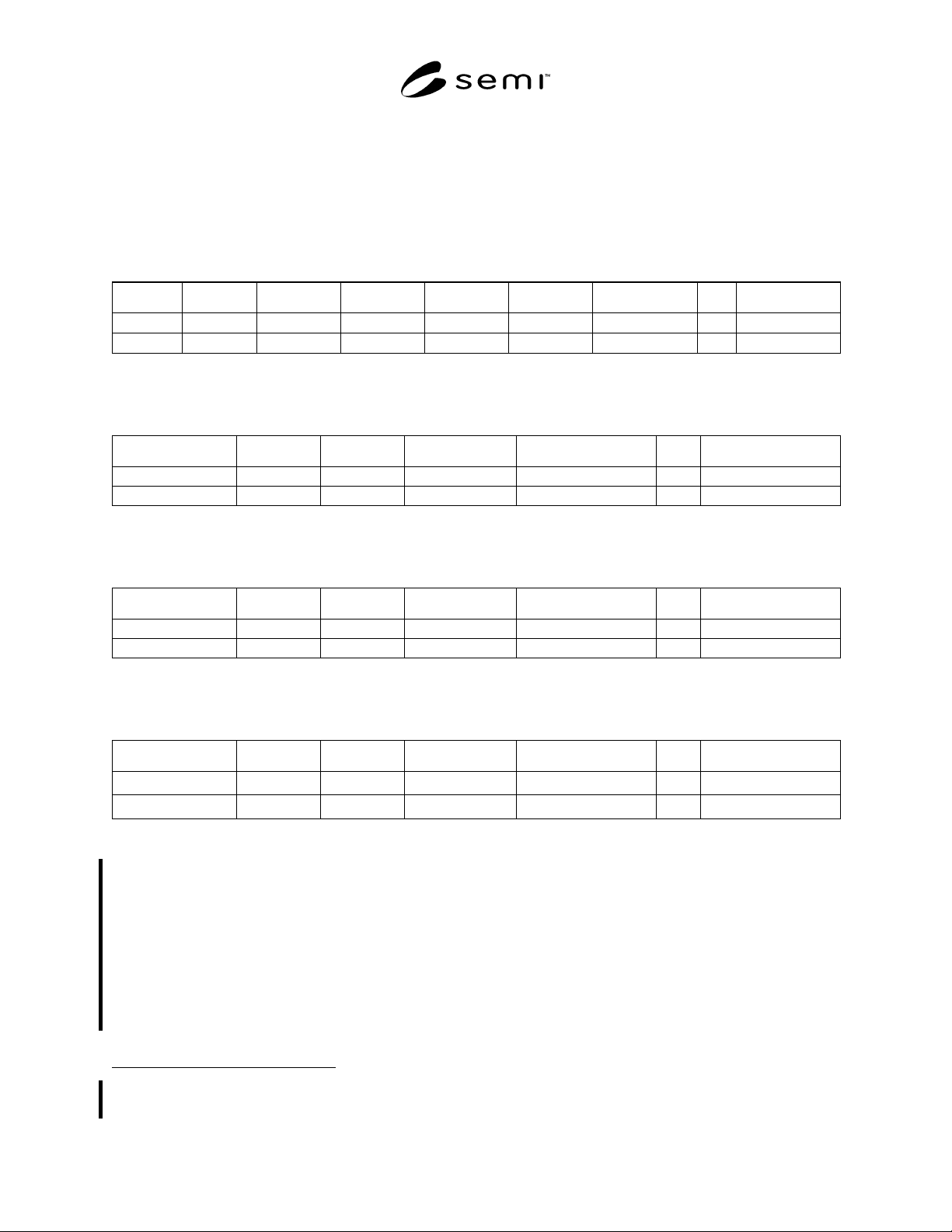
As indicated in Table 5, the SEMI M21 anomaly definition table “TABLE-M21-ANOMALY-DEF” is optional. The
others are required.
ISEM requires that the following columns be included in the TABLE-DEFs. Table 6 defines the column headers and
the allowed formats. Anomaly attributes and attribute headings are defined by the supplier, based on equipment
capability.
11.3.1 “TABLE-AREA-DEF”
TableType: “TableAreaDef” TableID: <AreaTableName>
Area Name Coordx Coordy Coordsys Xtentx Xtenty Attribute (1) … Attribute
11.3.2 “TABLE-ALIGN-DEF”
TableType: “TableAlignDef” TableID: <AlignTableName>
AlignName Coordx Coordy Coordsys Attribute (1) … Attribute(N)
11.3.3 “TABLE-ANOMALY-DEF”
TableType: “TableAnomalyDef” TableID: <AnomalyTableName>
Anomalyid Coordx Coordy Coordsys AnomalyAttribute … AnomalyAttribute
11.3.4 “TABLE-M21-ANOMALY-DEF”
TableType = “TableM21AnomalyDef” TableID = <M21AnomalyTableName>
Anomalyid Coordx Coordy Elementid AnomalyAttribute … AnomalyAttribute
Defect data shall be transferred between the host and inspection/review/analysis equipment using SEMI E5, S13,F13. Columns in the table are
defined by Table 11.3.5 below.
11.3.5 TABLE-STANDARD-DEFECT-DATA-SET-DEF
NOTE 1: Data for each substrate should be reported in column order shown below. Inspection tools should support relevant
columns (see NOTE 6). Review and analysis tools should support all columns. Multiple data entries (list format data items) are
allowed for a given attribute on a single defect.
NOTE 2: The inspection equipment must add a table attribute called “Substrate Header” (ATTRID). It must be a list that includes
the following items in the given order: LotID (A[1..16]), SubstrateID (A[1..16]), ProcessEquipmentID (A[1..16]), substrate
center
1
(L[2], CoordX (F4), CoordY (F4)) and centering method
2
(A[1..16]). Refer to Table 4, Variable Item Dictionary for
descriptions of these items.
NOTE 3: See SEMI M21 for (0,0) die location methodology.
1 Vector from the origin of the substrate coordinate system to nominal substrate center location.
2 CoordSys (e.g., “SEMI M20”, “SEMI M21”, “M21P”, etc).

SEMI 30.1-0200 © SEMI 1998, 200023
NOTE 4: Die origin is located at lower left-hand corner (LLHC).
NOTE 5: Data format must comply with the ISEM standard.
NOTE 6: In order to signify tool context, anomaly attributes are labeled as follows:
Column name starts with “insp*_” for inspection data, “rev*_” for defect review data, “and “anal*_” for analysis data, where “*”
is a numeric string that ensures each set of columns added is uniquely named (e.g., “rev1_” and “rev2_”).
NOTE 7: Inspection, review and analysis tools must add a table attribute called “insp*_ Header,” “rev*_Header” and
“anal*_Header” respectively (ATTRID) each time they add data to the table.
3
It must be a list that includes the following items in
the given order: EquipmentID (A[1..16]), EquipmentType (A[1..16]), OperatorID (A[1..16]), and CLOCK
4
(A[16]).
Column # Column Name Description
1 Insp_Anomaly ID ID # for the defect
2 Insp_Table specifier Specifies table with other relevant information
3 Insp_Coordinate X Intra die X Coordinate wrt LLHC of die in um
4 Insp_Coordinate Y Intra die Y Coordinate wrt LLHC of die in um
5 Insp_X index X axis die index wrt center of wafer (COW)
6 Insp_Y index Y axis die index wrt center of wafer (COW)
7 Insp_X size Defect size along X axis in microns
8 Insp_Y size Defect size along Y axis in microns
9 Insp_Defect area Defect area in square microns
10 Insp_Defect size Linear measure of defect size in microns
11 Insp_Scatter intensity Anomaly scattering intensity
12 Insp_Defect class number Previously defined class number assigned to the defect
13 Insp_Test number Inspection test in which defect was found
14 Insp_# Optical image count Number of optical images stored for a given defect
15 Insp_Optical image data Optical image data specifier
16 Insp_Cluster = 1 if defect is part of a systematic defect cluster
17 Insp_Cluster class Systematic defect class name
18 Sampled for SEM = 1 if defect chosen for SEM review
19 Rev_SEM image data SEM image data specifier
20 Rev_SEM class SEM defect class name
21 Rev_Defect height Defect height in microns
22 Sampled for analysis = 1 if defect chosen for EDX,
= 2 if defect chosen for FIB or other analysis
23 Anal_EDX data EDX data specifier
24 Anal_FIB data FIB data specifier
3 Where “*” is a numeric string that corresponds to the one in the column names the header refers to.
4 Date and time of the start of inspection, review, or analysis per SEMI E5 CLOCK data item variable.

SEMI 30.1-0200 © SEMI 1998, 2000 24
11.4 TABLE-DEF Column Header Descriptions and Formats
Table 6 Description and Formats for ISEM Table Data
Column Header Description Format Comments
“ALIGNNAME” The identifier given to an alignment site. A[1..16]
ANOMALYATTRIBUTE
(n) NOTE: String defined
by equipment supplier.
Tool-specific information associated
with an ANOMALY for which no
specific ISEM data item has been
defined.
U2, F4, F8,
A[1..16]
Examples: Include information such as
magnification, voltage, current,
wavelength, brightness, color, height,
or chemical spectra. The equipment
supplier shall document all attributes
that are supported.
“ANOMALYID” A unique identifier for an anomaly. A[1..16]
“AREANAME” A unique identifier given to an
inspection area.
A[1..16]
ATTRIBUTE(n)
NOTE: String defined by
equipment supplier.
Tool-specific information associated
with an alignment or measurement site
for which no specific ISEM data item
has been defined.
U2, F4, F8,
A[1..16]
Examples: Include information such as
magnification, voltage, current,
wavelength, number of scans,
integration time, or film stack. The
equipment supplier shall document all
attributes that are supported.
“COORDSYS” The identification for applicable
coordinate system.
A[1..16] Options are “M20”, “M20P”, and
“M21”.
“COORDX” The x-coordinate for a site. F4 Units are in microns.
“COORDY” The y-coordinate for a site. F4 Units are in microns.
“ELEMENTID” The SEMI M21 address for a specific
rectangular element on a substrate.
I4[2]
“XTENTX” The extent in the X-direction of an area
to inspect as measured from the lower
left-hand corner of the area given by
CoordX.
F4 Units in microns.
“XTENTY” The extent in the Y-direction of an area
to inspect measured from the lower left-
hand corner of the area given by
CoordY.
F4 Units in microns.
12 Process Program Management
12.1 Definition and Rules for ISEM Process Programs
12.1.1 A process program contains information and/or
instructions required for the Inspection/Review
equipment to process a given run of material. The
process program shall supply all of the information
required for a remotely executed run to be processed
without operator intervention.
12.2 Requirements
12.2.1 The ISEM requires that the SEMI E30
capability of Process Program Management be fully
supported for this class of equipment. ISEM requires
that the process program have a structure that enables
the user to build process programs with default
conditions that can be overridden for a run. ISEM
requires the ability to vary the quantity of substrates
processed, the alignment information used, and the
number and/or location of the areas/anomalies to be
inspected/reviewed through the uses of process program
variable parameters. The concepts of process program
structure and process program variable parameters are
discussed in the following sections.
12.3 Process Program Structure
12.3.1 The purpose of this process program structure
and the related concepts is to provide flexibility in
using process programs to reduce the number of process
programs needed. This structure enables the user or
host to vary certain parameters of a given process
program as needed for any particular run.
12.3.2 Often a process program may be very similar
from one run to another and may differ only in a few
parameters such as: which substrate slots to run, which
areas to inspect, which parameters to run on each
substrate, etc. Previously this small variation from run
to run would require a large number of process
programs to be created and maintained. The flexibility