semi合集-English.pdf - 第1913页
SEMI E54.1-1000 © SEMI 1996, 2000 19 Table 22 Excepti onDetailType Attribute Values for Alarm and Warning Reporting Meth ods Reporting M ethod Attribute Hig h Nibble V alue (Alarm) Attribute Low Nibble Value (W arning) B…
SEMI E54.1-1000 © SEMI 1996, 2000 18
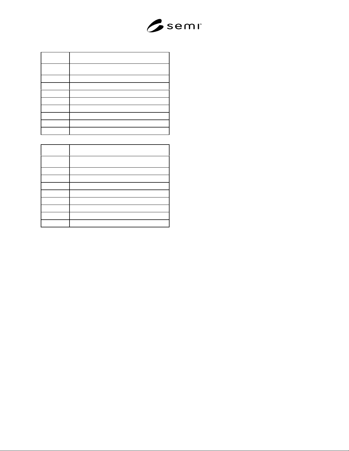
Table 21 Common Exception Detail Attribute Value
Common Exception Detail*
bit Detail[0]
0 internal diagnostic exception
1 microprocessor exception
2 EPROM exception
3 EEPROM exception
4 RAM exception
5 communications exception
6 internal real-time exception
7 calibration expiration
Common Exception Detail*
bit Detail[1]
0 power supply overcurrent
1 reserved power supply
2 power supply output voltage
3 power supply input voltage
4 routine maintenance due
5 notify manufacturer
6 reset exception
7 reserved
* Note that if a device does not support an exception detail, the
corresponding bit is never set.
7.3.1.15 Device Exception Detail (optional) — This
structure, similar in form to Common Exception Detail,
relates exception conditions which are specific to
individual devices on the network and are defined in
their respective device model documents. The Detail
element of the structure is an ordered list (i.e., array) of
bytes of length [SIZE] which is the value of the
structure element size. For a detailed description of this
attribute, consult the appropriate specific device model
documentation.
7.3.1.16 Manufacturer Exception Detail (optional) —
This structure, similar in form to Common Exception
Detail, relates exception conditions which are specific
to the manufacturers of individual devices on the
network and are defined by them in their product
documentation. The Detail element of the structure is
an ordered list (i.e., array) of bytes of length [SIZE]
which is the value of the structure element size. For a
detailed description of this attribute, consult the
appropriate specific device manufacturer
documentation.
Additional attributes may be supported by a DM object
that are device-specific. A complete definition of any
additional attributes may be found in an appropriate
sensor/actuator network specific device model
specification.
7.3.1.17 VisualIndicator (Optional) — An attribute
which defines the behavior of a visual indicator
allowing the device to be visually located. This attribute
is an enumerated byte that can take on one of the
following values:
0 = Visual Indicator OFF
1 = Visual Indicator ON
2–63 = Reserved
64–255 = Manufacturer-Specified
For values visual indicator OFF and visual indicator
ON, the visual indicator is defined to be a Light
Emitting Diode (LED). When the value is visual
indicator ON, the device is expected to flash the LED at
a frequency of approximately 0.5 to 1.5 Hz at a duty
cycle of approximately 30 to 70 percent. The location
and labeling of the LED are manufacturer-specified.
7.3.1.18 AlarmEnable (Optional) — An attribute
which defines whether or not the object will report
alarms (as indicated by the ReportingMode,
ExceptionStatus, ExceptionDetailType, and
ExceptionDetailAlarm attributes). When this attribute is
set to TRUE, then alarming is enabled. When this
attribute is set to FALSE, all DM exception attributes
are set and maintained at values that indicate a no alarm
state. Thus bits 0 through 2 of the ExceptionStatus
attribute are set and maintained at zero, and any
ExceptionDetailAlarm attribute bytes are set and
maintained at a value of zero.
7.3.1.19 WarningEnable (Optional) — An attribute
which defines whether or not the object will report
warnings (as indicated by the ReportingMode,
ExceptionStatus, ExceptionDetailType, and
ExceptionDetailWarning attributes). When this attribute
is set to TRUE, then warning exception reporting is
enabled. If this attribute is set to FALSE, all DM
exception attributes are set and maintained at values
that indicate a no warning state. Thus, bits 4 through 6
of the ExceptionStatus attribute are set and maintained
at zero, and any ExceptionDetailWarning attribute
bytes are set and maintained at a value of zero.
7.3.1.20 ExceptionDetailType (Optional) — An
attribute consisting of two enumerated nibbles that
designate the method of alarm and warning detail
reporting respectively that is supported. The possible
attribute values and corresponding reporting mode
support indications are enumerated in Table 22. Note
that if this attribute is not supported, the reporting mode
is either zero (basic) or one (expanded) as indicated in
bit seven of the ExceptionStatus attribute.
SEMI E54.1-1000 © SEMI 1996, 200019
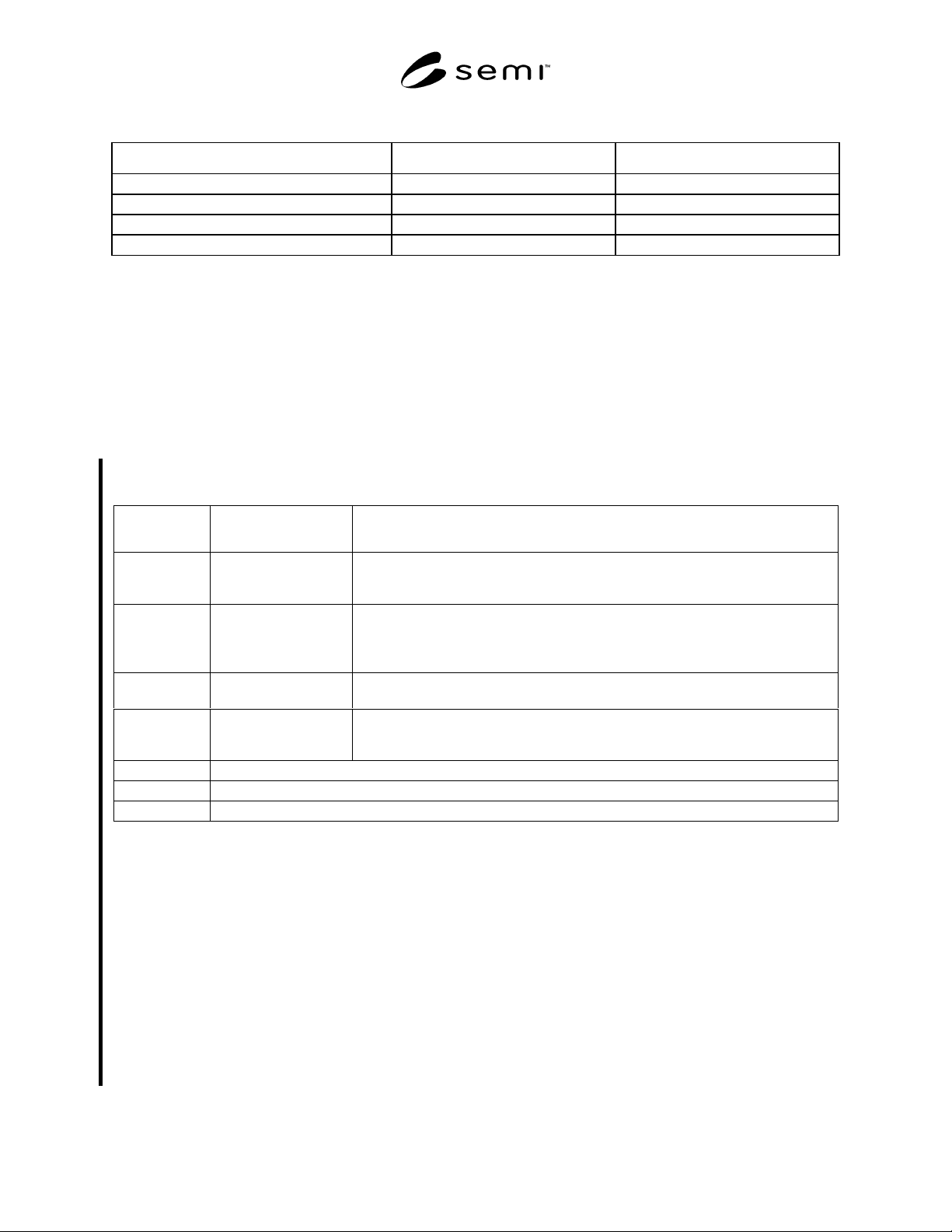
Table 22 ExceptionDetailType Attribute Values for Alarm and Warning Reporting Methods
Reporting Method Attribute High Nibble Value (Alarm) Attribute Low Nibble Value (Warning)
Basic 0 0
Expanded 1 1
Queued 2 2
Reserved for Future Extension of CDM 3 – 15 3 – 15
7.3.1.21 ExceptionDetailAlarmQueue (Optional) — An attribute consisting of an ordered list of alarm events; the
data structure of the individual alarm events (i.e., queue elements) is determined by the values of the
ExceptionStatus attribute; if bit 7 of the ExceptionStatus attribute indicates a Basic Mode reporting data format then
each queue element is of the same data type as ExceptionStatus; if bit 7 of the ExceptionStatus attribute indicates an
Expanded Mode reporting data format then each queue element is of the same data type as ExceptionDetail
(Alarm/Warning). The behavior of this queue in storing and reporting alarms is described in Section 7.3.3.
7.3.1.22 ExceptionDetailWarningQueue (Optional) — An attribute consisting of an ordered list of warning events;
the data structure is determined as described in Section 7.3.1.21. The behavior of this queue in storing and reporting
warnings is described in Section 7.3.3.
7.3.1.23 Date and Time — A structure that relates the current time as perceived by the device. The form of the
structure depends on the value of the Data and Time Type attribute as follows:
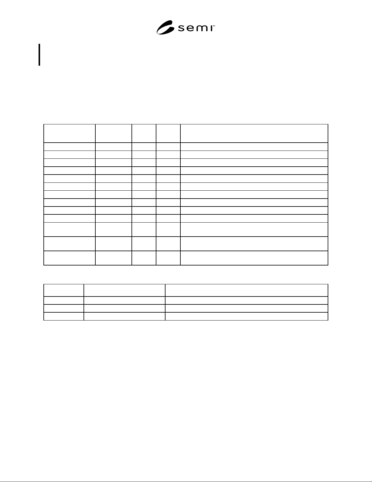
Date and
Time Type
Date and Time
Structure
Semantics
0 [default] Struct of:
UDINT
UINT
{Standard Time and Date} (6 Bytes)
Number of milliseconds since midnight
Number of days since 01 January, 1972
1 Struct of:
UDINT
UINT
INT
{Standard Time and Date with Offset} (8 Bytes)
Number of milliseconds since midnight
Number of days since 01 January, 1972
Number of minutes displacement from the Greenwich Meridian
2 Struct of:
LINT
{Universal Time Coordinated (UTC)} (8 Bytes)
Number of 100 nanoseconds since 15 October, 1582, 00:00:00
3 Struct of:
LINT
INT
{UTC with Time Displacement Factor} (10 Bytes)
Number of 100 nanoseconds since 15 October, 1582, 00:00:00
Number of minutes displacement from the Greenwich Meridian
4 - 63 Reserved
64 - 127 Specific Device Model definitions as required
128 - 255 Manufacturer specified as required
7.3.1.23.1 If the Date and Time Type attribute is not supported, the default value of zero (0) is assumed.
7.3.1.23.2 The Standard Time and Date (Type 0) uses 32 bits to represent the number of milliseconds since
midnight followed by 16 bits to represent the number of days since 01 January, 1972. The reference for this format
is either Greenwich Mean Time or Local Time as defined by the user. This format has a range of 01 January, 1972
to 06 June, 2151.
7.3.1.23.3 The Standard Time and Date with Offset (Type 1) uses the above format followed by 16 bits to represent
the number of minutes displacement from the Greenwich Meridian. Meridians to the East are positive, while those
to the West are negative.
7.3.1.23.4 The Universal Time Coordinated (UTC) (Type 2) is based on the format used by the WWV radio station
of NIST. It uses 64 bits to represent the number of 100 nanoseconds since 15 October, 1582, 00:00:00. The
reference for this format is always Greenwich Mean Time. This format has an approximate range of BC 27,000 to
AD 30,000.
SEMI E54.1-1000 © SEMI 1996, 2000 20
7.3.1.23.5 The UTC with Time Displacement Factor (TDF) (Type 3) uses the above format followed by 16 bits to
represent the number of minutes displacement from the Greenwich Meridian. Meridians to the East are positive,
while those to the West are negative.
7.3.2 DM Object Services — All DM object instances must provide the services listed in Table 23. (The DM object
is the “service provider” of these services.) Note that all of these services are Request services, with the exception of
the PublishAttribute service (which is a notification service). DM services are identified with a service identifier of
the form “DmSn”, where “n” is a positive decimal number. Dm service identifiers DmS1 through DmS8 are used by
this common device model standard. DM service identifiers DmS9 through DmS32 are reserved. Service parameters
that are specified in this standard are summarized in Table 24.
Table 23 DM Object Service Resource Definition
Service Service
Identifier
Required Type Description
Reset DmS1 Y R Used to place object in INITIALIZED state.
Abort DmS2 Y R Used to place object in ABORT state.
Recover DmS3 Y R Used to move object from ABORT state to RECOVERED state.
GetAttribute DmS4 Y R Used to read object attribute.
SetAttribute DmS5 Y R Used to modify object attribute.
Execute DmS6 Y R Used to move object from IDLE state to EXECUTING state.
PerformDiagnostics DmS7 Y R Used to instruct object to perform diagnostic test.
PublishAttribute DmS8 N N Used to proactively report exception status attribute.
Lock DmS9 N R Used to restrict access to READ only attributes.
Unlock DmS10 N R Used to make READ only attributes modifiable.
Get Exception Queue DmS11 N R Used to retrieve all, or a specified number of, exception events
from the front of the ExceptionDetailAlarm/WarningQueue.
Clear Exception
Queue
DmS12 N R Used to clear all exception events from the ExceptionDetail Alarm
or WarningQueue.
Reserved by CDM DmS13 –
DmS32
— — Reserved for CDM expansion.
Table 24 DM Object Service Parameter Dictionary
Parameter Form Description
AttributeID Enumerated DM object attribute identifier (see Table 17)
AttributeValue Context-specific (see Table 17) Value of DM object attribute.
TestID Non-negative integer, < 256 Type and possibly detail of diagnostic test to be performed.
A detailed description of these services follows.
7.3.2.1 Reset (Service Identifier: DmS1) — Used to place the DM object in its INITIALIZED state. There are no
parameters specified for this service.
7.3.2.2 Abort (Service Identifier: DmS2) — Used to place the DM object in its ABORT state. There are no
parameters specified for this service.
7.3.2.3 Recover (Service Identifier: D mS3) — Used to move the DM object from its ABORT state to a recovered
state (which is the IDLE state for this object). There are no parameters specified for this service.
7.3.2.4 GetAttribute (Service Identifier: DmS4) — Used to read a DM object attribute.