semi合集-English.pdf - 第6330页
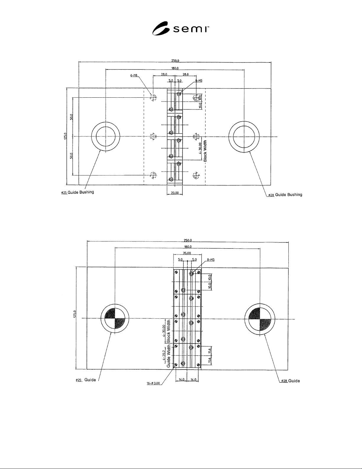
3 SEMI G65-96 © SEMI 1996, 2004 Figure 4 Upper Tool Detail Figure 5 Lower Tool Detail
SEMI G65-96 © SEMI 1996, 2004 2
5 Summary of Method
5.1 The leadframe samples (etched using a standard mask agreed between user and supplier) will be formed using a
“W” forming tool. The resulting form angle is to be measured and surface characteristics such as cracking and
orange peel are to be visible for compliance to the agreed upon specification.
6 Interference
6.1 If the forming tool does not meet the specification, lead movement during forming may result in poor
repeatability.
7 Significance
7.1 Devices manufactured with leadframes of different spring back characteristics may cause board assembly
problems, due to lead positional differences.
7.2 Crack in the leadframe may cause poor contact reliability with board.
8 Equipment
8.1 Tensile Tester — With minimum 9800N force and 1% accuracy.
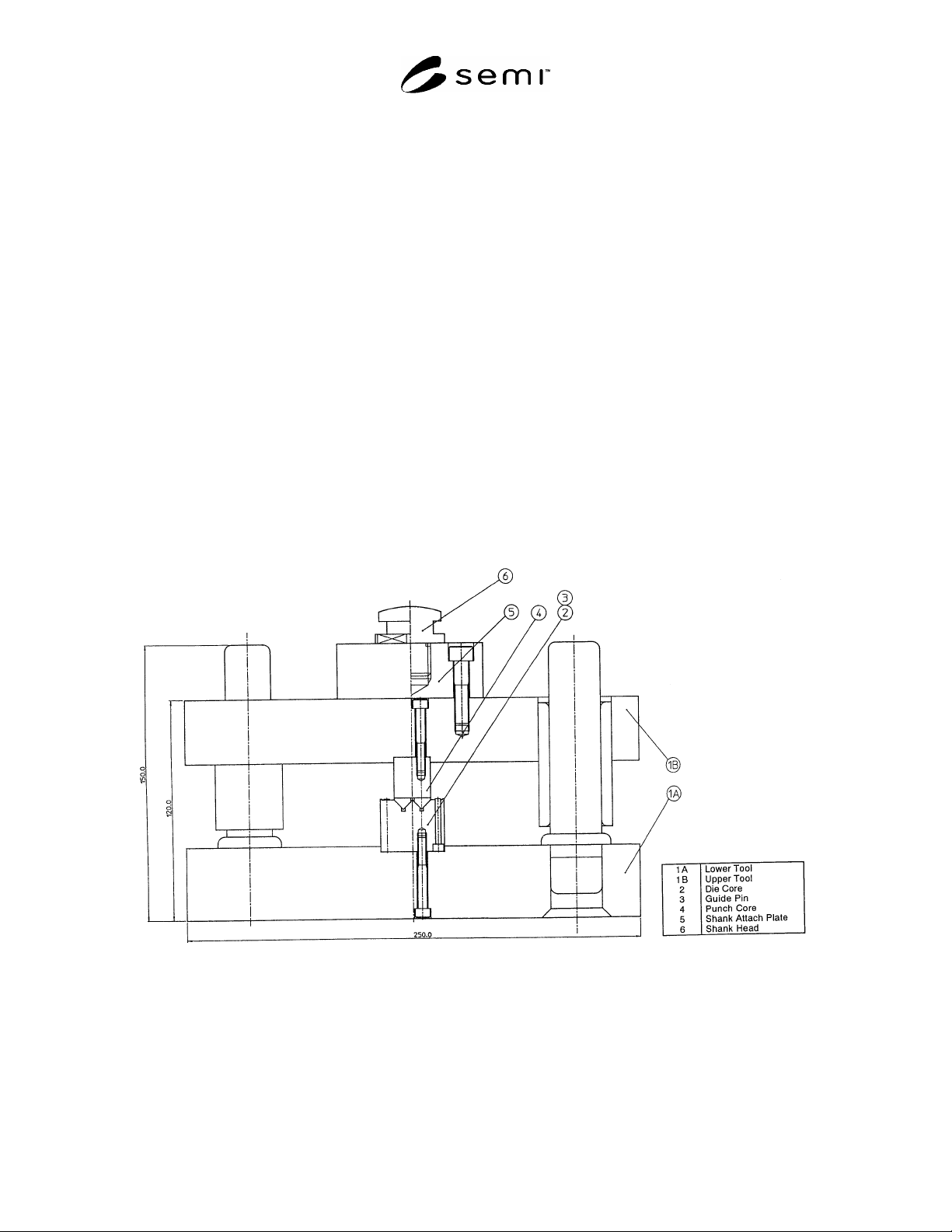
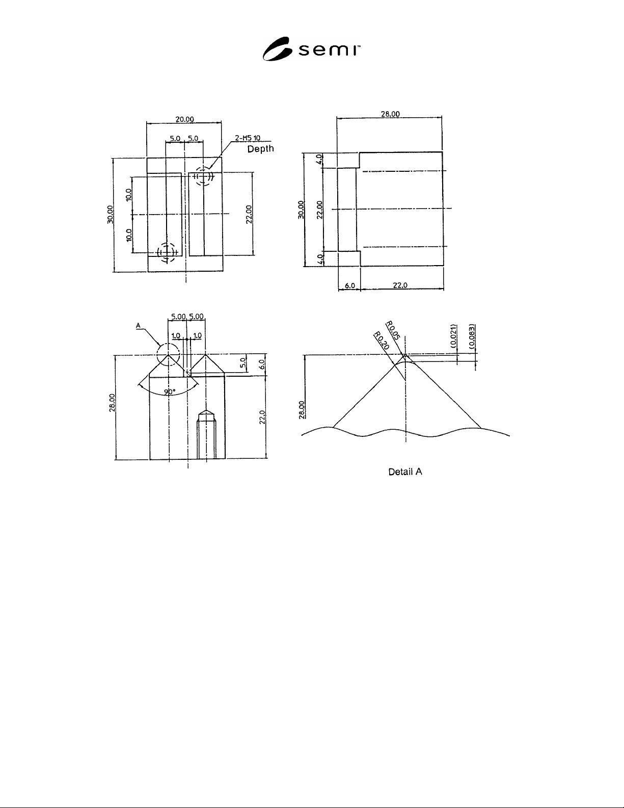
8.2 “W” Forming Tool — With R = 0, 0.1 and 0.2 and form angle of 90°. The dimension and configuration are
shown in Figures 3–7.
Figure 3
W-Bending Test Tool
3 SEMI G65-96 © SEMI 1996, 2004
Figure 4
Upper Tool Detail
Figure 5
Lower Tool Detail
SEMI G65-96 © SEMI 1996, 2004 4
Figure 6
Punch Core Detail